This thread has been locked.

If you have a related question, please click the "Ask a related question" button in the top right corner. The newly created question will be automatically linked to this question.

CCS/TMS320F28377D: IPCBOOT command caused a CPU2 to CPU1 IPC0 interrupt

Part Number: TMS320F28377D
Other Parts Discussed in Thread: C2000WARE

Tool/software: Code Composer Studio

Hi,

There is an issue with my project that I'm thinking you guys could help me with.

Background:

The project is being developed on two cpus. Codes are load in flash memories of both CPU while some of the time-oriented applications copied into RAM before running.

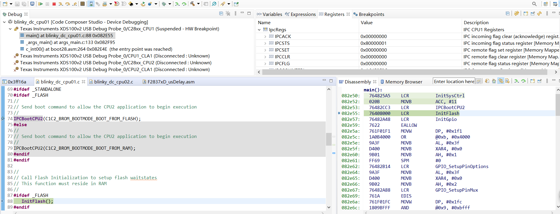
In CPU1, IPCBootCPU2(C1C2_BROM_BOOTMODE_BOOT_FROM_FLASH); command was used to boot CPU2 from FLASH.

When CPU1 and CPU2 both were connected with CCS and loaded with codes, the debug process was error-free. The application was running as it was designed.

Issue:

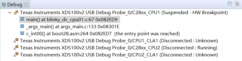
Step1: Some modifications had to be made in CPU1 application. After done that, I connected CPU1 to CCS while CPU2 remained disconnected(since I didn't change anything in CPU2 and it needn't to be debugged) with CCS to debug my codes in CPU1.

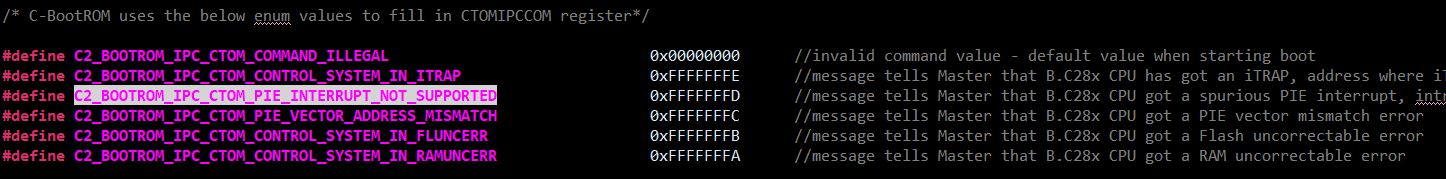
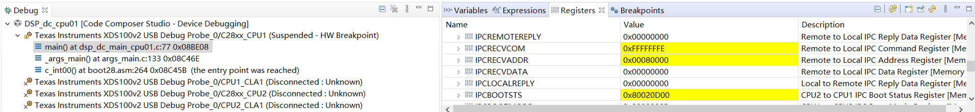
Step2: Under this condition, an IPC0 interrupt was received by CPU1 every time after IPCBootCPU2(C1C2_BROM_BOOTMODE_BOOT_FROM_FLASH) ;  was executed.

Step3: If CPU2 and CPU1 were both connected and loaded with codes, the issue disappeared. There was no IPC0 interrupt fired from CPU2 to CPU1.

Question:

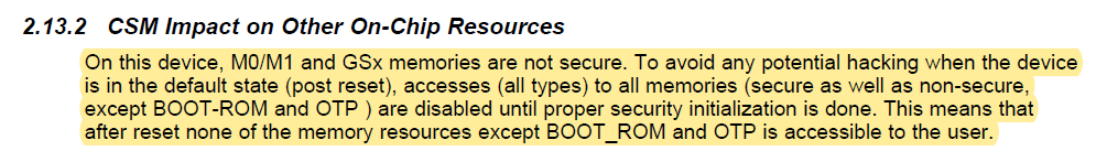
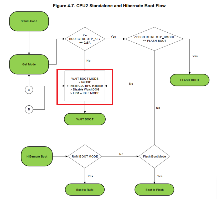
I was wondering what state the CPU2 was in when it was not connected with CCS(when only CPU1 was connected), so that it fired an IPC0 interrupt to CPU1.

I also looked through CPU2 bootrom code, and found out that there was no IPC0 interrupt fired. Normally it just run through the bootrom and in wait boot mode waiting for IPC command from CPU1.

I'm looking at the 'blinky_dc_cpu1' and 'blinky_dc_cpu2' dual-core example project provided in c2000_ware. It has the same issue if only CPU1 was connected and CPU2 disconnected.

Many thanks.

Best regards,

John

  • John,

    Table 4-12.Boot ROM Exceptions and Actions in Pg 616 in TRM summarizes the actions taken by CPU2 BOOT ROM on exceptions. To know what triggered IPC interrupt, please check CPU1.IPCRECVCOM, the value defined below will let you know the cause of the IPC interrupt.

      Regards,

    Manoj

  • Hi Manoj,

    I have checked content of CPU1.IPCRECVCOM, and it's 0xFFFFFFFE which indicates CPU2 encountered an ITRAP. Then I check the CPU1.IPCRECVADDR, and it's 0x080000, which means CPU2 encountered this error in address 0x080000.

    Here is what I still don't understand. Address 0x080000 is the address where I put my code_start branch codes and it's in FLASH memory. Since I have already loaded my code on CPU2 once before and didn't make any changes after that, it should remain intact. To verify this, after CPU1 received this ITRAP IPC0 interrupt from CPU2, I unplugged emulator and pressed the hardware reset button to reset the board. The application ran just fine. This indicates codes in CPU2 are ok. So the question remains. What is the status of CPU2 when only CPU1 is connected to CCS so that the IPC0 ITRAP was fired after CPU1 called the IPCBootCPU2(C1C2_BROM_BOOTMODE_BOOT_FROM_FLASH); function?

    Status of CPU1 IPC registers:

    Connect CPU2 to check 0x080000 content after this issue was encountered:

    Regards,

    John

  • John,

    Have you locked CPU2 device? My hypothesis is when CPU1 asks CPU2 code to execute from flash, since CPU2 is locked (DCSM) CPU fetches 0x0000 which illegal instruction.

    Can you confirm whether your device is locked? Both CPU1 and CPU2.

    Regards,

    Manoj

  • Hi Manoj,

    Thank you so much for your insight.

    DCSMs of both CPUs have never been changed since it's a new board. So I think all memories are unlocked as long as InitDCSM(); function is called.

    But I do have another hypothesis. Here is what I found in TRM.

    This means that if InitDCSM(); function is not called, then access to memory resources except BOOTROM and OTP is banned.

    I'm thinking maybe InitDCSM(); function has never been executed on CPU2 when CPU1 used IPCBootCPU2(C1C2_BROM_BOOTMODE_BOOT_FROM_FLASH); function to fire an IPC0 interrupt to CPU2 to force it boot from FLASH. And since InitDCSM(); function has not been executed, access to 0x080000 of CPU2 will be blocked. Then ITRAP ISR of CPU2 is entered to fire an IPC0 interrupt back to CPU1.

    But that would indicate CPU2 successfully entered IPC0 ISR and ITRAP ISR responding to the Boot command received from CPU1. And both ISR vectors have been properly initialized(maybe during CPU2 boot process in c2brom_system_init(); function). This contradicts the hypothesis that InitDCSM(); function has not been called, because in c2brom_system_init(); function, InitDCSM(); is called as well.

    Could you confirm that whether the debugger initializes ITRAP ISR vector and IPC0 ISR vector of CPU2, and leaves InitDCSM(); function not being executed when it's not connected?

    Regards,

    John

  • Hi John,

    Could you confirm that whether the debugger initializes ITRAP ISR vector and IPC0 ISR vector of CPU2, and leaves InitDCSM(); function not being executed when it's not connected?

    Debugger does not initialize any ISR but it does call InitDCSM() function in Gel file. Same is called inside BOOTROM code which should get executed if debugger is not connected.

    You mentioned that on CPU1 you load the code and then run it which means CPU1 BOOT ROM is not running where as since CPU2 is not connected after every reset CPU2 BOOTROM gets executed so I think this is making the full boot process a bit out of sync. Once you have loaded the CPU1 code, please issue debug reset and then set the emulation boot mode to boot to flash (on CCS click on "Scripts -> EMU Boot Mode Select -> EMU_BOOT_FLASH) and the click on "Run".  This will have CPU1 run BOOT code and then jump to CPU1 application code. Let us know if you still see the same issue.

    Regards,

    Vivek Singh

  • John,

    Below is the snapshot of CPU2 standalone boot. Before CPU2 is invoked to BOOT_TO_FLASH from CPU1, is CPU2 in IDLE mode? Also, please confirm whether you have secured the device with password?

    Regards,

    Manoj

  • Hi Manoj,

    Sorry for the late reply.

    I understand that normally CPU2 will enter IDLE mode and wait for CPU1's IPC commands for boot options. And this has been verified by connecting both CPUs to CCS and running a simple dual-core LED blinky project(like mentioned above). However, the issue occurs when I only connected CPU1 while left CPU2 unconnected with CCS to debug the same dual-core LED blinky project which is provided in C2000ware. The IPC0 interrupt fired from CPU2 to CPU1 after IPCBootCPU2(C1C2_BROM_BOOTMODE_BOOT_FROM_FLASH); function was called.

    Like I have said, CPU2 was not connected to CCS. So I don't know the status of it. The device is a brand new one. And I didn't touch any of the DCSM settings.

    Regards,

    John

  • Hi Vivek,

    Sorry for the late reply.

    I did some experiments as you suggested.

    Project used and settings are:

    1) blinky_dc project provided in C2000Ware_2_01_00_00_Software.

    2) Building configurations used for both CPUs are FLASH_STANDALONE.

    3) Only GPIO numbers were changed since on my board, the pins connected to LEDs are different.

    4) The compiler version is TI v20.2.0.LTS.

    Here are the steps I took to first make sure the codes are fine.

    1) Load CPU1 and CPU2 with the codes and connect both of them to CCS.

    2) Press reset in CCS to reset both CPUs. Then let CPU2 free run( to go into WAIT boot mode as designated in its boot_rom).

    3) Set a breakpoint right before the IPCBootCPU2(C1C2_BROM_BOOTMODE_BOOT_FROM_FLASH); funtion is called.

    4) Press run for CPU1. Program then stopped at breakpoint.

    5) Press 'Step Over' button to run IPCBootCPU2(C1C2_BROM_BOOTMODE_BOOT_FROM_FLASH); function.

    6) Issue did not occur. No IPC interrupts fired from CPU2 to CPU1.

    7) Press run for CPU1. LEDs were flashing as it should be.

    After the making sure the codes are fine, here are the steps I took when issue occurred now:

    1) Connect and load codes into CPU1 while leave CPU2 unconnected with CCS.

    2) Press reset button to 'CPU Reset' button to reset CPU1.

    3) Set a breakpoint right before the IPCBootCPU2(C1C2_BROM_BOOTMODE_BOOT_FROM_FLASH); funtion is called.

    4) Press run for CPU1. Program then stopped at breakpoint.

    5) Press 'Step Over' button to run IPCBootCPU2(C1C2_BROM_BOOTMODE_BOOT_FROM_FLASH); function. Then the same issue occurred.  IPC0 interrupt fired from CPU2 to CPU1.

    There is another thing that's been bothering me. After I click IPCSTS register to see the content of it, all bits have another bit with the same name of it. For example there are two IPC31, two IPC30, etc. Is this a bug of CCS? The version I'm using is CCS 10.0.0.00010.

    Regards,

    John

  • John,

    I tried the above procedure on example project available in below path and I didn't run into the issue you are talking. I didn't get any IPC interrupt from CPU2 and the code ran just fine.

    Path: C2000Ware_2_01_00_00\device_support\f2837xd\examples\dual\blinky_dc

    1) Connect and load codes into CPU1 while leave CPU2 unconnected with CCS.

    In the procedure you had mentioned you load your code in CPU1 and leave unconnected. That brings a question, did you program CPU2 blinky_dc_cpu02 application code into flash. If I make sure both CPU1 application code (blinky_dc_cpu01.out) and CPU2 application code (blinky_dc_cpu02.out) are indeed programmed in flash, I don't run into any issues.

    Based on what you are reporting, I get a feeling that you aren't programming CPU2 application code in flash. When that happens it is not surprising that CPU2 reporting illegal instruction fetch because it would have executed 0xFFFF (empty flash) which is illegal instruction.

    Regards,

    Manoj

  • Manoj,

    It's a bit strange.

    I made sure CPU2 was loaded with the right code by first load both blinky_dc_cpu01.out and blinky_dc_cpu02.out into CPU1 and CPU2 respectively. Then it was debugged with both CPUs being connected, and there was no issue.

    Immediately after that, I stopped the debug session, then start the debug again by loading CPU1 with blinky_dc_cpu01.out(CPU2 remained unconnected, shown below).

    Under this condition, the issue occurred. After pressing 'run' for both CPUs, only one LED was flashing. The one controlled by CPU2 didb't.

    To prove the right code had been loaded into CPU2. I reset the CPU1(without terminating the debug session), connected CPU2(without loading or anything. just simply connect CPU2 to see the disassembly. Results shown below)

    Then I pressed run for both CPU1 and CPU2. Both LEDs were flashing fine.

    Under this condition, I disconnected CPU2 again(without ending the current debug session). Then reset CPU1 in CCS. Then pressed 'run' again. The issue occurred with only one LED flashing(the one controlled by CPU2 didn't).

    So my hypothesis is that, when CPU2 was not connected with CCS, access to all memories except ROM are blocked.

    Regards,

    John

  • Hi John,

    After you connect CPU2, can you check the NMISHDFLG register in CPU2 and see if there is any flag set there ? 

    Regards,

    Vivek Singh

  • Also check the value at address 0x0000_0002 (BOOT Status) and let us know what is it.

    Regards,

    Vivek SIngh

  • John,

    The problem you are seeing is because of gel file (f28377d_cpu1.gel). When you connect to CPU1, f28377d_cpu1.gel executes OnReset(int nErrorCode) when you connect to the device. But, since you don't connect to CPU2, it doesn't execute f28377d_cpu2.gel file. This makes both CPU1 and CPU2 go out of sync.

    In f28377d_cpu1.gel file, when you connect to CPU1, it automatically bring CPU2 out of reset and holds CPU2 in idle mode but in locked state. So, when your CPU1 application code executes IPCBootCPU2(C1C2_BROM_BOOTMODE_BOOT_FROM_FLASH), CPU2 jumps to flash address 0x80000 which reads 0x0000 (this is an illegal instruction) and then it triggers ITRAP ISR.

    In order to avoid this scenario, you can possibly disable both CPU1 (f28377d_cpu1.gel) and CPU2 gel (f28377d_cpu2.gel) file and try executing CPU1 application code then both the LEDs will toggle as expected. So, this is more a CCS gel file issues and you don't need to be worried about it.

    Regards,

    Manoj

  • Manoj,

    It’s been confusing me for quite a while. Although it was hardly affecting my debug progress, I was just curious about this issue and would like to know the cause of it. Thank you so much for this. It makes sense now.

    Regards,

    John

  • Vivek,

    Thank you for your insights and efforts. What Manoj said clarified the issue.

    Regards,

    John