Recently we change the CAN configuration of the TMS320F28374D, to use the 1Mbps baud rate using a 200Mhz peripheral clock.
Now, we used the Texas API to initialize the CAN peripheral both in CPU1 and CPU2. Moore exactly we called the function
CANBitRateSet(gst_Can[e_CanPort].u32_CanAddrBase, 200000000L, 1000000L);
In this way the Can rate is set automatically, using a clock prescaler of 19 (real 19+1) and the following parameter (red color)
tatic const uint16_t g_ui16CANBitValues[] =
{
0x1100, // TSEG2 2, TSEG1 2, SJW 1, Divide 5
0x1200, // TSEG2 2, TSEG1 3, SJW 1, Divide 6
0x2240, // TSEG2 3, TSEG1 3, SJW 2, Divide 7
0x2340, // TSEG2 3, TSEG1 4, SJW 2, Divide 8
0x3340, // TSEG2 4, TSEG1 4, SJW 2, Divide 9
0x3440, // TSEG2 4, TSEG1 5, SJW 2, Divide 10
0x3540, // TSEG2 4, TSEG1 6, SJW 2, Divide 11
0x3640, // TSEG2 4, TSEG1 7, SJW 2, Divide 12
0x3740 // TSEG2 4, TSEG1 8, SJW 2, Divide 13
};
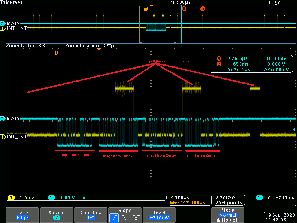
Nevertheless, once the transmitting unit send 4 messages continuously, 1usec far from each other, sometimes the DSP loose one message.
The Can queue is 14 messages depth, so we are not explaining why we are facing this problem.
Can you help us please?
P.S. we have already tried to set the configuration register to 0x0700 instead of 0x3440, following the example in the manua, but the problem was still there. Sometimes the DSP don’t receive a message.
Thank you for your help,
Andrea Marcianesi.