This thread has been locked.

If you have a related question, please click the "Ask a related question" button in the top right corner. The newly created question will be automatically linked to this question.

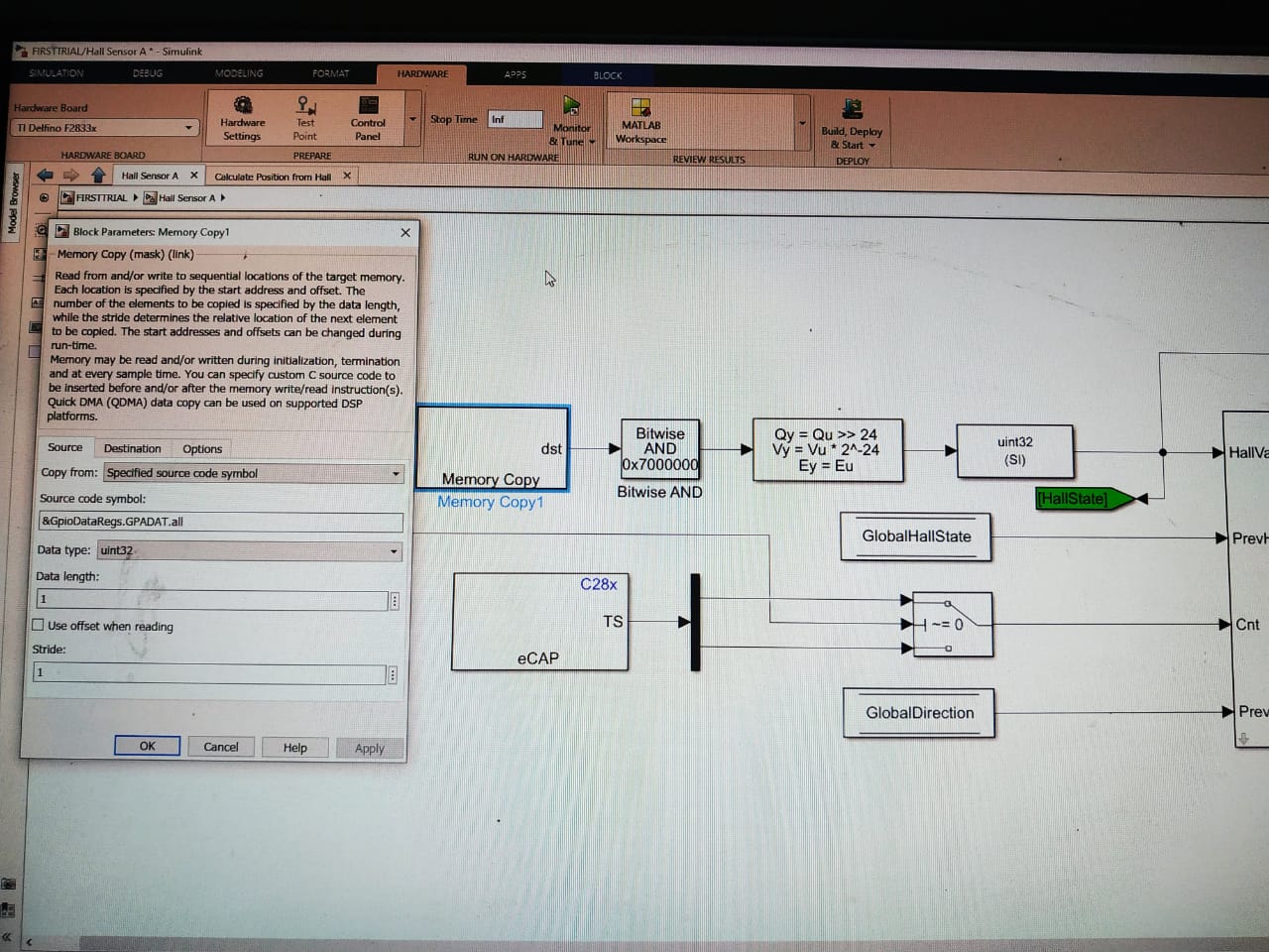
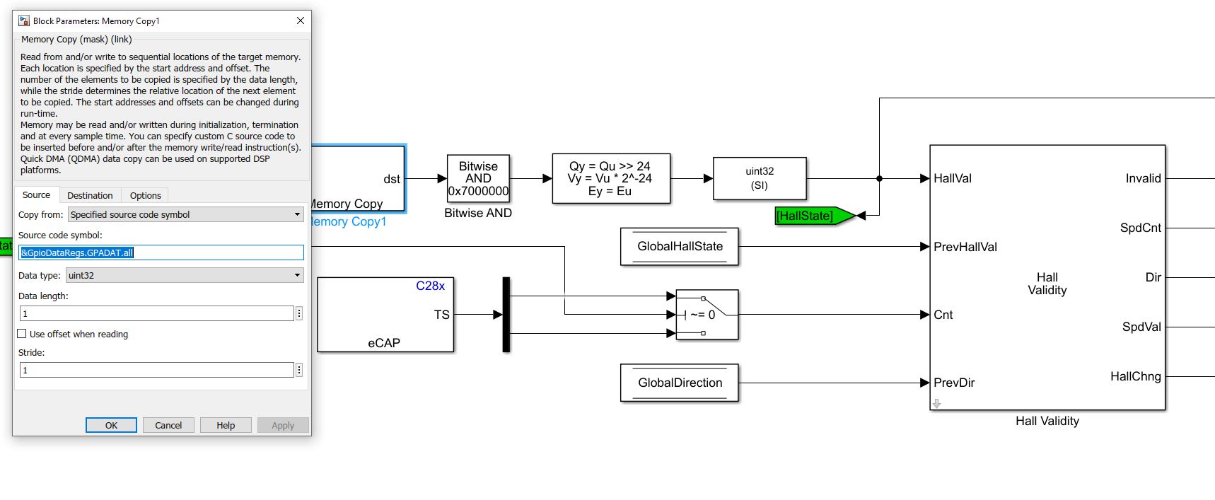
TMS320F28335: GPADAT.all is performed a bitwise and with 0x7000000 and later its went through a arithmetic shifter with the conditions as in screenshot attached can any one explain me the reason behind all of this

Part Number: TMS320F28335

please can one explain me the reason behind all that conversion and motive behind it.

thanks in advance

s.chand 

  • Saichand,

    This looks like an example from the MW package, can you clarify which example this is coming from?  Have you also posted on the MW forum, this appears to be their example code.

    Best,

    Matthew

  • Matthew,

    yes this is a matlab example on offset computation with hall sensor (open_system('mcb_pmsm_hall_offset_f28069m.slx');).

    I am completely new to 28335,so can u please explain me about GPADAT.all and the reason for and operation with 0x7000000.

    Best regards

    s.chand

  • S.chand,

    GPADAT is both a read/write register that shows the state of the GPIOA 0-31 but can also be used to change the state of those GPIOs when written to.  I would refer to the F2833x TRM Section 1.4 for more information on the register sets and their functions.

    In terms of the AND 0x70000000, it appears that the MW code is reading something from the GPIOA bus, but only keeping bits GPIO28-30 to store in the on-chip memory.

    Best,
    Matthew

  • Thank you for your response Mr. Matthew pate

    And operation is performed with 0x07000000 to all gpio data May I know how did you determine that gpio 28-30 were selected . If I want to select 34-37 then I should be performing with which hexadecimal no?

    Thanks in advance

    S. Chand

  • S. Chand,

    It looks like I mis-read the screen image you posted, and the AND is 0x07000000 as you pointed out.  So in this case the MW code is keeping bits 24-26, essentially the GPADAT in this case is GPIO0-31 with each bit representing the state of the GPIO##.

    For higher GPIOs, as you mentioned 34-37, these are on the GPBDAT register.  The C28x is a 32-bit CPU so you'll see the largest register group is usually a long, i.e. 32-bit.

    Best,

    Matthew

  • Matthew Pate,

    Thank you for response.

    please can you mention the hexadecimal number one should be to read data from any random pin like 45,38 or any.

    thank you for your patience and help in making me understand  can you just please answer this above question and it would resolve my entire concept on this.

    best regards

    s.chand

  • S. Chand,

    Can you comment on the HW board you are using externally?  Is this a TI reference design(if so please copy the link to the page on TI.com)?  We would need to look at the schematic to see what is attached to these GPIO pins to understand what kind of data is coming across.

    In terms of any GPIO if it is forced to 3.3V(high) the corresponding GPxDAT bit will read a "1".  If the GPIO is forced to ground(0V) then it will read a 0.

    In the above MW block there must be some variable data/signal on these IO pins that will influence the code.

    Best,

    Matthew

  • Matthew Pate,

    I beg your pardon for late response. As u suggested me to go through sprui07 i have been lately going through it, this really helped me understand  about GPIO and its control registers and all of your previous answers are making a lot more sense now.
    the matlab example is trying to read the signals coming off of hall sensors on to Ecap modules at GPIO 24 25 26 ecap1 ,ecap2 and ecap3 respectively with GPAMUX2 bits set to 01.Even i understood about GPADAT it defines the state of pin 0 for low and 1 for high and it can also change the state of pin if it is  configured as  GPIO output .

    But all i couldn't understand is the GPIO pins 24 25 26 are used as Ecap to read hall sensor signals which will be a grey code of 1 3 2 6 4 5 or  5 4 6 2 3 1 for CW and CCW rotation of motor respectively hence signal at each pin will be high for 180 deg ,low for rest 180 deg and 120 phase shift between each pin signal.

    "So if we are masking the GPADAT.ALL with 0x07000000, it will set GPIO pins 24 25 26  always high  irrespective of hall sensor signals  and wont be able to read the change in  hall sensor signals." this statement is all what i concluded my self but i feel iam wrong so can u please clear me with this misconception.

    Best Regards

    S.Chand 


  • Part Number: TMS320F28335

    Tool/software: Code Composer Studio

    in a matlab simulink example to read the signals off of hall sensors ,eCAP 1,2 and 3 are used located at gpio 24 25 and 26 with GPAMUX2 BITS SETS TO 01. The data register of port A i.e, GPADAT.all is  AND operated with 0x07000000.
    I am confused with this operation if we perform AND on GPADAT.ALL with 0x07000000 pin no 24 25 and 26 are having binary equivalent equal to 1 and rest all pins have 0, if they are always set to 1 how can they detect change in hall signals because hall signals  generate a grey code so signal from each hall sensor will be high for 180 deg and low for another 180 deg.
     
    the example which i mentioned is offset calculation of hall sensors matlab example  :   open_system('mcb_pmsm_hall_offset_f28069m.slx');

  • S. Chand,

    I really appreciate you investigating this further, as to what the meaning of these pins in the system is.  

    In this case the MW team is using the AND of 0x07000000 to only read GPIOs 26-24 when they get the whole GPIO bus.  If the GPIO is set it will come through, if not it will stay cleared, all other GPIOs will be ignored which is correct.

    You'll notice in the next block there is a shift right of 24 bits, to get these 3 bits in the LSB of the variable.

    I noticed that there is a new post around this same topic, I'm going to merge it here to keep the info in the same place.

    Best,

    Matthew

  • Matthew Pate

    Thank you so much for answering all my questions and responding to my queries.
     

    Best regards
     

    s.chand

  • Mattew Pate 

    With ur immense support I could finally read the signals coming off of hall sensors but the processor is able to detect the change in signal when the rotor is rotating at very low speed like less than 10rpm.but if it is rotating at speed above 10 rpm it's not able to pick up the signals properly I have attached the waveforms at two speeds.
    I request your suggestion on this problem.
    Best
    s.chand

  • S. Chand,

    I'm going to ask a colleague to look into you last post that has more experience with the encoding side of things.

    Best,

    Matthew

  • Hello,

    If the GPIOs are read (sampled) in a while loop with no time sensitivity, then there could be such issues. Ideally, the GPIOs should be read in a high speed ISR to capture the transitions better. 

    Alternately, the problem could be in reporting the data out at a slower rate.

  • Dear sir,

    Thank you for your reply actually I am not coding rather using Matlab simulink 2020a to read my GPIOs and I am facing this difficulty. can you please explain in brief about ISR mode or refer any example so that it would help me in understanding it a better way.I am attaching the matlab simulation file and the program which I am using to read the GPIO 24 25 26 as eCAP peripherals.
    I sincerely request your help with this. Thanks in advance.

    Best regards

    s.chand

    /*
    * File: halloffset1.c
    *
    * Code generated for Simulink model 'halloffset1'.
    *
    * Model version : 1.816
    * Simulink Coder version : 9.3 (R2020a) 18-Nov-2019
    * C/C++ source code generated on : Thu Sep 17 14:37:44 2020
    *
    * Target selection: ert.tlc
    * Embedded hardware selection: Texas Instruments->C2000
    * Code generation objectives: Unspecified
    * Validation result: Not run
    */

    #include "halloffset1.h"
    #include "halloffset1_private.h"
    #include "halloffset1_dt.h"

    /* Block signals (default storage) */
    BlockIO_halloffset1 halloffset1_B;

    /* Block states (default storage) */
    D_Work_halloffset1 halloffset1_DWork;

    /* Real-time model */
    RT_MODEL_halloffset1 halloffset1_M_;
    RT_MODEL_halloffset1 *const halloffset1_M = &halloffset1_M_;

    /* Hardware Interrupt Block: '<Root>/C28x Hardware Interrupt' */
    void isr_int4pie1_task_fcn(void)
    {
    /* Call the system: <Root>/Subsystem */
    {
    /* Reset subsysRan breadcrumbs */
    srClearBC(halloffset1_DWork.Output0.Output0_SubsysRanBC);

    /* Reset subsysRan breadcrumbs */
    srClearBC(halloffset1_DWork.Subsystem_SubsysRanBC);

    /* S-Function (c28xisr_c2000): '<Root>/C28x Hardware Interrupt' */

    /* Output and update for function-call system: '<Root>/Subsystem' */

    /* Asynchronous task reads absolute time. Data (absolute time)
    transfers from low priority task (base rate) to high priority
    task (asynchronous rate). Double buffers are used to ensure
    data integrity.
    -- rtmL2HLastBufWr is the buffer index that is written last.
    */
    halloffset1_M->Timing.clockTick1 =
    halloffset1_M->Timing.rtmL2HDbBufClockTick
    [halloffset1_M->Timing.rtmL2HLastBufWr];
    halloffset1_M->Timing.clockTickH1 =
    halloffset1_M->Timing.rtmL2HDbBufClockTickH
    [halloffset1_M->Timing.rtmL2HLastBufWr];

    /* S-Function (memorycopy): '<S1>/Memory Copy1' */
    {
    uint32_T *memindsrc = (uint32_T *) (&GpioDataRegs.GPADAT.all);
    uint32_T *meminddst = (uint32_T *) (&halloffset1_B.MemoryCopy1_k);
    *(uint32_T *) (meminddst) = *(uint32_T *) (memindsrc);
    }

    /* S-Function (sfix_bitop): '<S1>/Bitwise AND' */
    halloffset1_B.BitwiseAND_hx = halloffset1_B.MemoryCopy1_k &
    halloffset1_P.BitwiseAND_BitMask;

    /* ArithShift: '<S1>/Shift Arithmetic' */
    halloffset1_B.ShiftArithmetic_i = halloffset1_B.BitwiseAND_hx >> 24U;

    /* DataTypeConversion: '<S1>/Data Type Conversion' */
    halloffset1_B.DataTypeConversion_p = halloffset1_B.ShiftArithmetic_i;

    /* S-Function (c280xcap): '<S1>/eCAP' */
    {
    halloffset1_B.eCAP_n1[0] = ECap1Regs.CAP1;
    halloffset1_B.eCAP_n1[1] = ECap1Regs.CAP2;
    }

    /* If: '<S4>/If' */
    if ((halloffset1_B.DataTypeConversion_p == 5UL) ||
    (halloffset1_B.DataTypeConversion_p == 3UL)) {
    /* Outputs for IfAction SubSystem: '<S4>/Output 0' incorporates:
    * ActionPort: '<S5>/Action Port'
    */
    halloffset1_Output0(&halloffset1_B.Merge_k, &halloffset1_P.Output0);

    /* End of Outputs for SubSystem: '<S4>/Output 0' */
    } else {
    /* Outputs for IfAction SubSystem: '<S4>/Output 1' incorporates:
    * ActionPort: '<S6>/Action Port'
    */
    halloffset1_Output0(&halloffset1_B.Merge_k, &halloffset1_P.Output1);

    /* End of Outputs for SubSystem: '<S4>/Output 1' */
    }

    /* End of If: '<S4>/If' */

    /* Switch: '<S1>/Switch' */
    if (halloffset1_B.Merge_k) {
    halloffset1_B.Switch_c = halloffset1_B.eCAP_n1[0];
    } else {
    halloffset1_B.Switch_c = halloffset1_B.eCAP_n1[1];
    }

    /* End of Switch: '<S1>/Switch' */
    halloffset1_DWork.Subsystem_SubsysRanBC = 4;

    /* End of Outputs for S-Function (c28xisr_c2000): '<Root>/C28x Hardware Interrupt' */
    }
    }

    /* Hardware Interrupt Block: '<Root>/C28x Hardware Interrupt' */
    void isr_int4pie2_task_fcn(void)
    {
    /* Call the system: <Root>/Subsystem1 */
    {
    /* Reset subsysRan breadcrumbs */
    srClearBC(halloffset1_DWork.Subsystem1_SubsysRanBC);

    /* S-Function (c28xisr_c2000): '<Root>/C28x Hardware Interrupt' */

    /* Output and update for function-call system: '<Root>/Subsystem1' */

    /* Asynchronous task reads absolute time. Data (absolute time)
    transfers from low priority task (base rate) to high priority
    task (asynchronous rate). Double buffers are used to ensure
    data integrity.
    -- rtmL2HLastBufWr is the buffer index that is written last.
    */
    halloffset1_M->Timing.clockTick2 =
    halloffset1_M->Timing.rtmL2HDbBufClockTick
    [halloffset1_M->Timing.rtmL2HLastBufWr];
    halloffset1_M->Timing.clockTickH2 =
    halloffset1_M->Timing.rtmL2HDbBufClockTickH
    [halloffset1_M->Timing.rtmL2HLastBufWr];

    /* S-Function (memorycopy): '<S2>/Memory Copy1' */
    {
    uint32_T *memindsrc = (uint32_T *) (&GpioDataRegs.GPADAT.all);
    uint32_T *meminddst = (uint32_T *) (&halloffset1_B.MemoryCopy1_o);
    *(uint32_T *) (meminddst) = *(uint32_T *) (memindsrc);
    }

    /* S-Function (sfix_bitop): '<S2>/Bitwise AND' */
    halloffset1_B.BitwiseAND_h = halloffset1_B.MemoryCopy1_o &
    halloffset1_P.BitwiseAND_BitMask_d;

    /* ArithShift: '<S2>/Shift Arithmetic' */
    halloffset1_B.ShiftArithmetic_j = halloffset1_B.BitwiseAND_h >> 24U;

    /* DataTypeConversion: '<S2>/Data Type Conversion' */
    halloffset1_B.DataTypeConversion_h = halloffset1_B.ShiftArithmetic_j;

    /* S-Function (c280xcap): '<S2>/eCAP' */
    {
    halloffset1_B.eCAP_n[0] = ECap2Regs.CAP1;
    halloffset1_B.eCAP_n[1] = ECap2Regs.CAP2;
    }

    /* If: '<S7>/If' */
    if ((halloffset1_B.DataTypeConversion_h == 3UL) ||
    (halloffset1_B.DataTypeConversion_h == 6UL)) {
    /* Outputs for IfAction SubSystem: '<S7>/Output 1' incorporates:
    * ActionPort: '<S9>/Action Port'
    */
    halloffset1_Output0(&halloffset1_B.Merge_e, &halloffset1_P.Output1_f);

    /* End of Outputs for SubSystem: '<S7>/Output 1' */
    } else {
    /* Outputs for IfAction SubSystem: '<S7>/Output 0' incorporates:
    * ActionPort: '<S8>/Action Port'
    */
    halloffset1_Output0(&halloffset1_B.Merge_e, &halloffset1_P.Output0_i);

    /* End of Outputs for SubSystem: '<S7>/Output 0' */
    }

    /* End of If: '<S7>/If' */

    /* Switch: '<S2>/Switch' */
    if (halloffset1_B.Merge_e) {
    halloffset1_B.Switch_g = halloffset1_B.eCAP_n[0];
    } else {
    halloffset1_B.Switch_g = halloffset1_B.eCAP_n[1];
    }

    /* End of Switch: '<S2>/Switch' */
    halloffset1_DWork.Subsystem1_SubsysRanBC = 4;

    /* End of Outputs for S-Function (c28xisr_c2000): '<Root>/C28x Hardware Interrupt' */
    }
    }

    /* Hardware Interrupt Block: '<Root>/C28x Hardware Interrupt' */
    void isr_int4pie3_task_fcn(void)
    {
    /* Call the system: <Root>/Subsystem2 */
    {
    /* Reset subsysRan breadcrumbs */
    srClearBC(halloffset1_DWork.Subsystem2_SubsysRanBC);

    /* S-Function (c28xisr_c2000): '<Root>/C28x Hardware Interrupt' */

    /* Output and update for function-call system: '<Root>/Subsystem2' */

    /* Asynchronous task reads absolute time. Data (absolute time)
    transfers from low priority task (base rate) to high priority
    task (asynchronous rate). Double buffers are used to ensure
    data integrity.
    -- rtmL2HLastBufWr is the buffer index that is written last.
    */
    halloffset1_M->Timing.clockTick3 =
    halloffset1_M->Timing.rtmL2HDbBufClockTick
    [halloffset1_M->Timing.rtmL2HLastBufWr];
    halloffset1_M->Timing.clockTickH3 =
    halloffset1_M->Timing.rtmL2HDbBufClockTickH
    [halloffset1_M->Timing.rtmL2HLastBufWr];

    /* S-Function (memorycopy): '<S3>/Memory Copy1' */
    {
    uint32_T *memindsrc = (uint32_T *) (&GpioDataRegs.GPADAT.all);
    uint32_T *meminddst = (uint32_T *) (&halloffset1_B.MemoryCopy1);
    *(uint32_T *) (meminddst) = *(uint32_T *) (memindsrc);
    }

    /* S-Function (sfix_bitop): '<S3>/Bitwise AND' */
    halloffset1_B.BitwiseAND = halloffset1_B.MemoryCopy1 &
    halloffset1_P.BitwiseAND_BitMask_b;

    /* ArithShift: '<S3>/Shift Arithmetic' */
    halloffset1_B.ShiftArithmetic = halloffset1_B.BitwiseAND >> 24U;

    /* DataTypeConversion: '<S3>/Data Type Conversion' */
    halloffset1_B.DataTypeConversion = halloffset1_B.ShiftArithmetic;

    /* S-Function (c280xcap): '<S3>/eCAP' */
    {
    halloffset1_B.eCAP[0] = ECap3Regs.CAP1;
    halloffset1_B.eCAP[1] = ECap3Regs.CAP2;
    }

    /* If: '<S10>/If' */
    if ((halloffset1_B.DataTypeConversion == 5UL) ||
    (halloffset1_B.DataTypeConversion == 6UL)) {
    /* Outputs for IfAction SubSystem: '<S10>/Output 1' incorporates:
    * ActionPort: '<S12>/Action Port'
    */
    halloffset1_Output0(&halloffset1_B.Merge, &halloffset1_P.Output1_e);

    /* End of Outputs for SubSystem: '<S10>/Output 1' */
    } else {
    /* Outputs for IfAction SubSystem: '<S10>/Output 0' incorporates:
    * ActionPort: '<S11>/Action Port'
    */
    halloffset1_Output0(&halloffset1_B.Merge, &halloffset1_P.Output0_c);

    /* End of Outputs for SubSystem: '<S10>/Output 0' */
    }

    /* End of If: '<S10>/If' */

    /* Switch: '<S3>/Switch' */
    if (halloffset1_B.Merge) {
    halloffset1_B.Switch = halloffset1_B.eCAP[0];
    } else {
    halloffset1_B.Switch = halloffset1_B.eCAP[1];
    }

    /* End of Switch: '<S3>/Switch' */
    halloffset1_DWork.Subsystem2_SubsysRanBC = 4;

    /* End of Outputs for S-Function (c28xisr_c2000): '<Root>/C28x Hardware Interrupt' */
    }
    }

    /*
    * Output and update for action system:
    * '<S4>/Output 0'
    * '<S4>/Output 1'
    * '<S7>/Output 1'
    * '<S7>/Output 0'
    * '<S10>/Output 1'
    * '<S10>/Output 0'
    */
    void halloffset1_Output0(boolean_T *rty_Out1, rtP_Output0_halloffset1 *localP)
    {
    /* SignalConversion generated from: '<S5>/Out1' incorporates:
    * Constant: '<S5>/Constant'
    */
    *rty_Out1 = localP->Constant_Value;
    }

    /* Model step function */
    void halloffset1_step(void)
    {
    /* External mode */
    rtExtModeUploadCheckTrigger(1);

    { /* Sample time: [0.2s, 0.0s] */
    rtExtModeUpload(0, (real_T)halloffset1_M->Timing.taskTime0);
    }

    /* signal main to stop simulation */
    { /* Sample time: [0.2s, 0.0s] */
    if ((rtmGetTFinal(halloffset1_M)!=-1) &&
    !((rtmGetTFinal(halloffset1_M)-halloffset1_M->Timing.taskTime0) >
    halloffset1_M->Timing.taskTime0 * (DBL_EPSILON))) {
    rtmSetErrorStatus(halloffset1_M, "Simulation finished");
    }

    if (rtmGetStopRequested(halloffset1_M)) {
    rtmSetErrorStatus(halloffset1_M, "Simulation finished");
    }
    }

    /* Update absolute time for base rate */
    /* The "clockTick0" counts the number of times the code of this task has
    * been executed. The absolute time is the multiplication of "clockTick0"
    * and "Timing.stepSize0". Size of "clockTick0" ensures timer will not
    * overflow during the application lifespan selected.
    * Timer of this task consists of two 32 bit unsigned integers.
    * The two integers represent the low bits Timing.clockTick0 and the high bits
    * Timing.clockTickH0. When the low bit overflows to 0, the high bits increment.
    */
    if (!(++halloffset1_M->Timing.clockTick0)) {
    ++halloffset1_M->Timing.clockTickH0;
    }

    halloffset1_M->Timing.taskTime0 = halloffset1_M->Timing.clockTick0 *
    halloffset1_M->Timing.stepSize0 + halloffset1_M->Timing.clockTickH0 *
    halloffset1_M->Timing.stepSize0 * 4294967296.0;

    {
    /* Base rate updates double buffers of absolute time for
    asynchronous task. Double buffers are used to ensure
    data integrity when asynchronous task reads absolute
    time.
    -- rtmL2HLastBufWr is the buffer index that is written last.
    */
    boolean_T bufIdx = !halloffset1_M->Timing.rtmL2HLastBufWr;
    halloffset1_M->Timing.rtmL2HDbBufClockTick[bufIdx] =
    halloffset1_M->Timing.clockTick0;
    halloffset1_M->Timing.rtmL2HDbBufClockTickH[bufIdx] =
    halloffset1_M->Timing.clockTickH0;
    halloffset1_M->Timing.rtmL2HLastBufWr = bufIdx;
    }
    }

    /* Model initialize function */
    void halloffset1_initialize(void)
    {
    /* Registration code */

    /* initialize real-time model */
    (void) memset((void *)halloffset1_M, 0,
    sizeof(RT_MODEL_halloffset1));
    rtmSetTFinal(halloffset1_M, -1);
    halloffset1_M->Timing.stepSize0 = 0.2;

    /* External mode info */
    halloffset1_M->Sizes.checksums[0] = (282413321U);
    halloffset1_M->Sizes.checksums[1] = (1854811080U);
    halloffset1_M->Sizes.checksums[2] = (145774513U);
    halloffset1_M->Sizes.checksums[3] = (3160180442U);

    {
    static const sysRanDType rtAlwaysEnabled = SUBSYS_RAN_BC_ENABLE;
    static RTWExtModeInfo rt_ExtModeInfo;
    static const sysRanDType *systemRan[10];
    halloffset1_M->extModeInfo = (&rt_ExtModeInfo);
    rteiSetSubSystemActiveVectorAddresses(&rt_ExtModeInfo, systemRan);
    systemRan[0] = &rtAlwaysEnabled;
    systemRan[1] = (sysRanDType *)&halloffset1_DWork.Output0.Output0_SubsysRanBC;
    systemRan[2] = (sysRanDType *)&halloffset1_DWork.Output1.Output0_SubsysRanBC;
    systemRan[3] = (sysRanDType *)&halloffset1_DWork.Subsystem_SubsysRanBC;
    systemRan[4] = (sysRanDType *)
    &halloffset1_DWork.Output0_i.Output0_SubsysRanBC;
    systemRan[5] = (sysRanDType *)
    &halloffset1_DWork.Output1_f.Output0_SubsysRanBC;
    systemRan[6] = (sysRanDType *)&halloffset1_DWork.Subsystem1_SubsysRanBC;
    systemRan[7] = (sysRanDType *)
    &halloffset1_DWork.Output0_c.Output0_SubsysRanBC;
    systemRan[8] = (sysRanDType *)
    &halloffset1_DWork.Output1_e.Output0_SubsysRanBC;
    systemRan[9] = (sysRanDType *)&halloffset1_DWork.Subsystem2_SubsysRanBC;
    rteiSetModelMappingInfoPtr(halloffset1_M->extModeInfo,
    &halloffset1_M->SpecialInfo.mappingInfo);
    rteiSetChecksumsPtr(halloffset1_M->extModeInfo,
    halloffset1_M->Sizes.checksums);
    rteiSetTPtr(halloffset1_M->extModeInfo, rtmGetTPtr(halloffset1_M));
    }

    /* block I/O */
    (void) memset(((void *) &halloffset1_B), 0,
    sizeof(BlockIO_halloffset1));

    /* states (dwork) */
    (void) memset((void *)&halloffset1_DWork, 0,
    sizeof(D_Work_halloffset1));

    /* data type transition information */
    {
    static DataTypeTransInfo dtInfo;
    (void) memset((char_T *) &dtInfo, 0,
    sizeof(dtInfo));
    halloffset1_M->SpecialInfo.mappingInfo = (&dtInfo);
    dtInfo.numDataTypes = 14;
    dtInfo.dataTypeSizes = &rtDataTypeSizes[0];
    dtInfo.dataTypeNames = &rtDataTypeNames[0];

    /* Block I/O transition table */
    dtInfo.BTransTable = &rtBTransTable;

    /* Parameters transition table */
    dtInfo.PTransTable = &rtPTransTable;
    }

    /* SystemInitialize for S-Function (c28xisr_c2000): '<Root>/C28x Hardware Interrupt' incorporates:
    * SubSystem: '<Root>/Subsystem'
    */
    /* System initialize for function-call system: '<Root>/Subsystem' */

    /* Asynchronous task reads absolute time. Data (absolute time)
    transfers from low priority task (base rate) to high priority
    task (asynchronous rate). Double buffers are used to ensure
    data integrity.
    -- rtmL2HLastBufWr is the buffer index that is written last.
    */
    halloffset1_M->Timing.clockTick1 = halloffset1_M->
    Timing.rtmL2HDbBufClockTick[halloffset1_M->Timing.rtmL2HLastBufWr];
    halloffset1_M->Timing.clockTickH1 =
    halloffset1_M->Timing.rtmL2HDbBufClockTickH
    [halloffset1_M->Timing.rtmL2HLastBufWr];

    /* SystemInitialize for S-Function (c28xisr_c2000): '<Root>/C28x Hardware Interrupt' incorporates:
    * SubSystem: '<Root>/Subsystem1'
    */
    /* System initialize for function-call system: '<Root>/Subsystem1' */

    /* Asynchronous task reads absolute time. Data (absolute time)
    transfers from low priority task (base rate) to high priority
    task (asynchronous rate). Double buffers are used to ensure
    data integrity.
    -- rtmL2HLastBufWr is the buffer index that is written last.
    */
    halloffset1_M->Timing.clockTick2 = halloffset1_M->
    Timing.rtmL2HDbBufClockTick[halloffset1_M->Timing.rtmL2HLastBufWr];
    halloffset1_M->Timing.clockTickH2 =
    halloffset1_M->Timing.rtmL2HDbBufClockTickH
    [halloffset1_M->Timing.rtmL2HLastBufWr];

    /* SystemInitialize for S-Function (c28xisr_c2000): '<Root>/C28x Hardware Interrupt' incorporates:
    * SubSystem: '<Root>/Subsystem2'
    */

    /* System initialize for function-call system: '<Root>/Subsystem2' */

    /* Asynchronous task reads absolute time. Data (absolute time)
    transfers from low priority task (base rate) to high priority
    task (asynchronous rate). Double buffers are used to ensure
    data integrity.
    -- rtmL2HLastBufWr is the buffer index that is written last.
    */
    halloffset1_M->Timing.clockTick3 = halloffset1_M->
    Timing.rtmL2HDbBufClockTick[halloffset1_M->Timing.rtmL2HLastBufWr];
    halloffset1_M->Timing.clockTickH3 =
    halloffset1_M->Timing.rtmL2HDbBufClockTickH
    [halloffset1_M->Timing.rtmL2HLastBufWr];

    /* End of SystemInitialize for S-Function (c28xisr_c2000): '<Root>/C28x Hardware Interrupt' */
    }

    /* Model terminate function */
    void halloffset1_terminate(void)
    {
    /* (no terminate code required) */
    }

    /*
    * File trailer for generated code.
    *
    * [EOF]
    */

  • It will be difficult for us to get into user code details, suggest to try from working examples with appropriate EVM and start experimenting from there.

  • Thank you for your reply sir

    Can you just please explain me what do you mean by high speed ISR and EVM. I am completely new to this yet I am working my way through it.

    Thanks in advance

    Best

    S. Chand

  • Hi,

    I won't be able to help you with your main topic in this thread, however I did want to mention that we have a F28335 Training Workshop that is available.  I'd recommend taking a look at it & going through it.  It's an investment of time, but usually worth it.  The workshop should give you a better foundation of knowledge on the C2000 architecture & terminology.
    https://training.ti.com/c2000-f2833x-microcontroller-workshop

    (ISR = interrupt service routine; EVM = evaluation module / development kit)


    Thank you,
    Brett