This thread has been locked.

If you have a related question, please click the "Ask a related question" button in the top right corner. The newly created question will be automatically linked to this question.

LAUNCHXL-F280049C: need help on increasing bit rate with PLC example code

Part Number: LAUNCHXL-F280049C
Other Parts Discussed in Thread: AFE031,

Hi support,
I am working on the example code: boostxl_afe031_f28004x_dacmode and boostxl_afe031_f28004x_rx. The bit rate is set to 1/5.12ms=195bps, which is way too slow. I tried to increase it by 10 times with following mod:
#define EPWM2_TIMER_TBPRD 1600 // (on _dacmode)
#define EPWM2_TIMER_TBPRD 1067 // EPwm2 Period register, 10666 ==> 586Hz (on _rx)
The signal output from the TX board looks fine, but there's no respond with the RX board. However when I tried with 2 times
#define EPWM2_TIMER_TBPRD 8000 // (on _dacmode)
#define EPWM2_TIMER_TBPRD 5334 // (on _rx)
Then it works fine.
Can you help to point out what I did wrong?
Thanks,
Eric

  • Hi Support,

    Just found one more line need to update on boostxl_afe031_f28004x_rx_main.c:

    FSK_struct1.bit_freq = 586;   // change to 5859

    but it still doesn't work.

    Eric

  • Hi,

    Your configuration for 10x seems correct to me but I would suggest  you to once profile the ISRs and background loop to ensure the bit stream frequency is not too high leading to missing of interrupts which can ultimately result in message timeout.

    If my reply answers your question please click on "This resolved my issue" button located at the bottom of my post.

    Regards

    Himanshu

  • Hi Himanshu,

    Thanks for your suggestion. After re-looking into FSK_CORR_DETECTOR_BITRATE_RUN & FSK_CORR_DETECTOR_OverSampl_RUN functions, I noticed that the detection equation is related to the bit frequency. If the bit frequency is changed, the threshold might need to change too. I tried to increased the threshold and found that it started to detect mark/space signals again! Looks like 0.3 is a good value for 10x bit frequency (5859Hz) after couples of trying. But is there a way to calculate out what value it should be for a specific bit frequency?

    Thanks,

    Eric

  • Hi Himanshu,

    After x10, the data bit rate will be 1953bps. What kind of  Maximum bit rate it can reach for this specific configuration (Fmark=131.25kHz / Fspace=143.75kHz)?

    And there are 2 more questions:

    1) Can you show me how to merge boostxl_afe031_f28004x_dacmode  and boostxl_afe031_f28004x_rx into one project? Especially how to change WPWM1 & EPWM2 to WPWM3 & EPWM4 or what ever.

    2) How to put the TX PA in sleep likely mode? Just disable PA or PA_OUT bit? There's almost no heat generated from Rx board, but it is always some kind of hot with Tx board even no data is transmitted.

    Thanks,

    Eric

  • Hi Eric,

    Glad to hear you were able to get higher bit rates working with the example code.

    Regarding the detection_threshold value, the easiest way to find a proper value is testing with a solid Mark / Space signal. There are a number of factors that will affect the working detection threshold, i.e. ADC sampling rate used, bit rate of FSK protocol, noise in system, etc.

    While there is likely a way to calculate a theoretical detection_threshold value for your operating conditions, the actual working threshold value will be slightly different (likely lower).

    Eric_L said:
    After x10, the data bit rate will be 1953bps. What kind of  Maximum bit rate it can reach for this specific configuration (Fmark=131.25kHz / Fspace=143.75kHz)?

    I'm not certain what the max achievable bit rate with this configuration will be. There are a number of factors that go into this, such as how frequent the ADC sample + RX algorithm can be run (CPU utilization will be a factor to consider). The example solution has not been tested by TI at higher bit rates than what is in the example by default.

    Eric_L said:
    1) Can you show me how to merge boostxl_afe031_f28004x_dacmode  and boostxl_afe031_f28004x_rx into one project? Especially how to change WPWM1 & EPWM2 to WPWM3 & EPWM4 or what ever.

    Are you trying to use ePWM3 / 4 for the RX or TX portion? It should be just changing the ePWM init functions and EPwmxRegs accordingly. Is there any specific part that's giving you trouble? ISRs will need to be adjusted accordingly as well.

    Best,

    Kevin

  • Hi Eric,

    Q2) How to put the TX PA in sleep likely mode? Just disable PA or PA_OUT bit? There's almost no heat generated from Rx board, but it is always some kind of hot with Tx board even no data is transmitted.

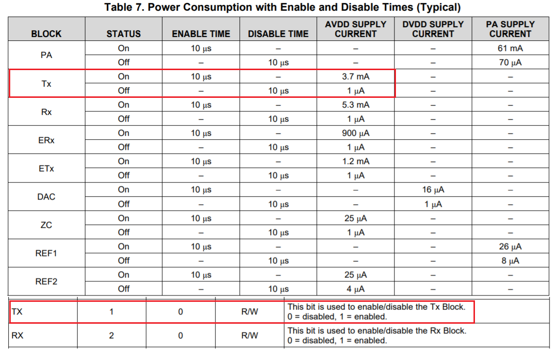
    You may be disable the Tx bit via AFE031's 0x01 register, see Table 11. Even the Tx status bit is not disable, it should only consume 3.3V*3.7mA=0.012W or 12mW, which is should not get warm (This is all allocated inside of AFE031). Can you tell me which IC that is felt some kind of hot on the board or on the schematic? Tx bit and its functions are a part of integrated AFE031 IC, and it is not allocated on a board. 

    If you have any questions, please let me know. 

    Best,

    Raymond

  • Hi Kevin,

    I am thinking to use ePWM3/4 for TX portion. But it should be able to use ePWM1/2 for both tx and rx with reconfiguration between switching, right?

    Now I am struggling with switching between tx and rx. I tried

    HAL_afe031_txDisable();
    HAL_afe031_dacDisable();
    HAL_afe031_rxEnable();
    HAL_afe031_cfgInt();

    But looks it won't work.

    Any suggestions are appreciated.

    Thanks,

    Eric

  • Hi Eric,

    Eric_L said:
    I am thinking to use ePWM3/4 for TX portion. But it should be able to use ePWM1/2 for both tx and rx with reconfiguration between switching, right?

    This may be possible, but you'll have to completely reconfigure the ePWMs and corresponding ISRs between TX and RX portions, rather than having a one time configuration if using separate ePWM pairs for both TX and RX.

    What you have for changing from TX to RX looks right to me for the AFE side. Have you configured the RX portions as well? i.e. ePWM driven ISRs, ADC, RX algorithm variables, etc.

    best,

    Kevin

  • Hi Kevin,

    I am focused on ePWM1/2 for RX and ePWM3/4 for TX now. Does DMA_EPWM1A in following line of xxx_dacmode_main.c need to be changed to DMA_EPWM3A?

    DMACH1ModeConfig(DMA_EPWM1A,PERINT_ENABLE,ONESHOT_DISABLE,CONT_ENABLE,
    SYNC_DISABLE,SYNC_SRC,OVRFLOW_DISABLE,SIXTEEN_BIT,
    CHINT_END,CHINT_ENABLE);

    Yes, I tried to add the following between the switching:

    RX ---> TX
    HAL_afe031_rxDisable();
    HAL_afe031_dacEnable();
    HAL_afe031_txDACEnable();
    HAL_afe031_cfgInt();

    TX ---> RX
    HAL_afe031_dacDisable();
    HAL_afe031_txDisable();
    HAL_afe031_rxEnable();
    HAL_afe031_cfgInt();

    But I can't get it working. How about the timers and interrupts? Should they be disable too before to switch to the other portion? Such as

    EPwm4Regs.ETSEL.bit.INTEN = 0; // Disable INT
    PieCtrlRegs.PIEIER7.bit.INTx1 = 0; // Disable PIE Group 7, INT 1 (DMA CH1)

    I even tried to re-initialize between tx/rx switch, however, it just able to switch from rx to tx but not able get back to rx after finishing transmission.

    Please help to point out what else I should try?

    Thanks,

    Eric

  • Hi Eric,

    Eric_L said:
    Does DMA_EPWM1A in following line of xxx_dacmode_main.c need to be changed to DMA_EPWM3A?

    Yes, change it to DMA_EPWM3A. This is configuring EPWM3 to trigger the DMA for the TX dacmode implementation.

    Have you been able to get the TX solution working with ePWM3/4 separately before integrating TX and RX together? Might be a good idea if having issues getting TX to work at all with ePWM3/4.

    Eric_L said:
    How about the timers and interrupts? Should they be disable too before to switch to the other portion?

    Stopping the respective TX or RX ePWMs when not in use should be sufficient to stop the interrupts from occurring.

    See the Start_Receiving(); and Stop_Receiving(); functions within the RX software and the pwm_enable(); function in the TX software for this purpose.

    Eric_L said:
    I even tried to re-initialize between tx/rx switch, however, it just able to switch from rx to tx but not able get back to rx after finishing transmission.

    Did you stop the TX ePWMs when switching back to RX? You'll want to stop ePWM interrupts from occurring for the disabled funcitonality.

    Best,

    Kevin

  • Hi Kevin,

    Have you been able to get the TX solution working with ePWM3/4 separately before integrating TX and RX together?  YES

    Did you stop the TX ePWMs when switching back to RX?  

    Is these 3 lines enough?

    EPwm4Regs.ETSEL.bit.INTEN = 0; // Disable INT
    pwm_enable(0);
    EPwm4Regs.ETCLR.bit.INT = 1;     // Clear INT flag for this timer

    Thanks,

    Eric

  • Hi Eric,

    What you have should work, you really just need the pwm_enable(0); function for stopping the TX PWMs as the example SW does. In the pwm_enable() function declaration you've updated the EPwm regs for 3 and 4 like the below? The TB_FREEZE command will stop the ePWM counters.

    void pwm_enable(Uint16 enable)
    {
        if (enable)
        {
            EPwm3Regs.TBCTL.bit.CTRMODE = TB_COUNT_UPDOWN;
            EPwm4Regs.TBCTL.bit.CTRMODE = TB_COUNT_UPDOWN;
        }
        else
        {
            EPwm3Regs.TBCTL.bit.CTRMODE = TB_FREEZE;
            EPwm4Regs.TBCTL.bit.CTRMODE = TB_FREEZE;
            // IMPORTANT: Delay to complete current SPI transaction
            DELAY_US(1000);
        }
    }

    To debug if ePWM interrupts are being disabled and re-enabled correctly for the TX and RX modes in CCS you can place break points in the respective ISR functions. That way you can check if the ISRs are being entered or not at different times.

    TX ISRs would be:

    • dma_isr (Should be configured for ePWM3 interrupt)
    • epwm4_isr

    And RX ISRs would be:

    • adc_sample_signal (Should be configured for ePWM1 interrupt)
    • epwm2_isr

    Best,

    Kevin

  • Hi Kevin,

    The pwm_enable ( ) is a bit hard to control since it is used on PA over current and thermal shut down monitoring. 

    I tried to use interrupt as:

    main()
    {
        ...
        PieCtrlRegs.PIECTRL.bit.ENPIE = 1; // Enable the PIE block
        PieCtrlRegs.PIEIER3.bit.INTx4 = 1; // EPWM4
        PieCtrlRegs.PIEIER7.bit.INTx1 = 1; // Enable PIE Group 7, INT 1 (DMA CH1)
        ...

        pwm_enable(0);
        EPwm4Regs.ETCLR.bit.INT = 1;
        EPwm4Regs.ETSEL.bit.INTEN = 0;

        while(1)
        {
             if (pushButton == YES)
             {
                EPwm4Regs.ETCLR.bit.INT = 1;
                EPwm4Regs.ETSEL.bit.INTEN = 1;
                Transmit();
            }

        }

    }

    __interrupt void epwm4_isr(void)
    {
            ...
            if (cycleCount == frameSize+1)
            {
                ...
                txChar = NaN;
                pwm_enable(0);
                EPwm4Regs.ETSEL.bit.INTEN = 0;
                EPwm4Regs.ETCLR.bit.INT = 1;
                ...
             }
    }

    However,  it will need to push RST in order to get into while (1) loop after power up. If I change the line before while (1) loop to EPwm4Regs.ETSEL.bit.INTEN = 1 or just remove it, then it'll get into while loop directly, but also runs ISR which is not expected. 

    Please help to explain what is the issue and how to fix it.

    Thanks,

    Eric

  • Hi Eric,

    The issue you're having isn't clear to me. Some of the functions and variables in your code are custom and not familiar to me as they're not in the example project, such as the 'pushButton' variable and the Transmit() function.

    Eric_L said:
    However,  it will need to push RST in order to get into while (1) loop after power up.

    What are you meaning by RST? I assume you don't mean the S1 XRSn button on the F28004x LaunchPad, since that resets the device and will disconnect the debugger.

    Eric_L said:
    If I change the line before while (1) loop to EPwm4Regs.ETSEL.bit.INTEN = 1 or just remove it, then it'll get into while loop directly, but also runs ISR which is not expected. 

    Maybe you have INTEN being set to 1 somewhere else in your code? Try searching your code for the same line. Setting this register to 1 will enable interrupt generations on the configured PWM event, as you probably know already.

    Best,

    Kevin

  • Hi Kevin,

    The pushButton is just an added function to detect a switch input on one of the GPIO pin, the transmit() is just moving the tx section codes which is preciously in main() to a single function,  and the RST is exact the S1 XRSn on the side edge of the LAUNCHXL-F280049C. My question is: what is the different between power up and S1 XRSn (reset?) ?

    Thanks,

    Eric

  • Hi Eric,

    The differences in reset sources are described in the table below and furthermore in the device datasheet. See Power on Reset (POR) and XRSn reset in the datasheet for more info. The behavior your seeing between the two is still confusing to me.

    Best,

    Kevin