This thread has been locked.

If you have a related question, please click the "Ask a related question" button in the top right corner. The newly created question will be automatically linked to this question.

TMS320F28062F: Vibration with IPM motor

Part Number: TMS320F28062F
Other Parts Discussed in Thread: C2000WARE-MOTORCONTROL-SDK

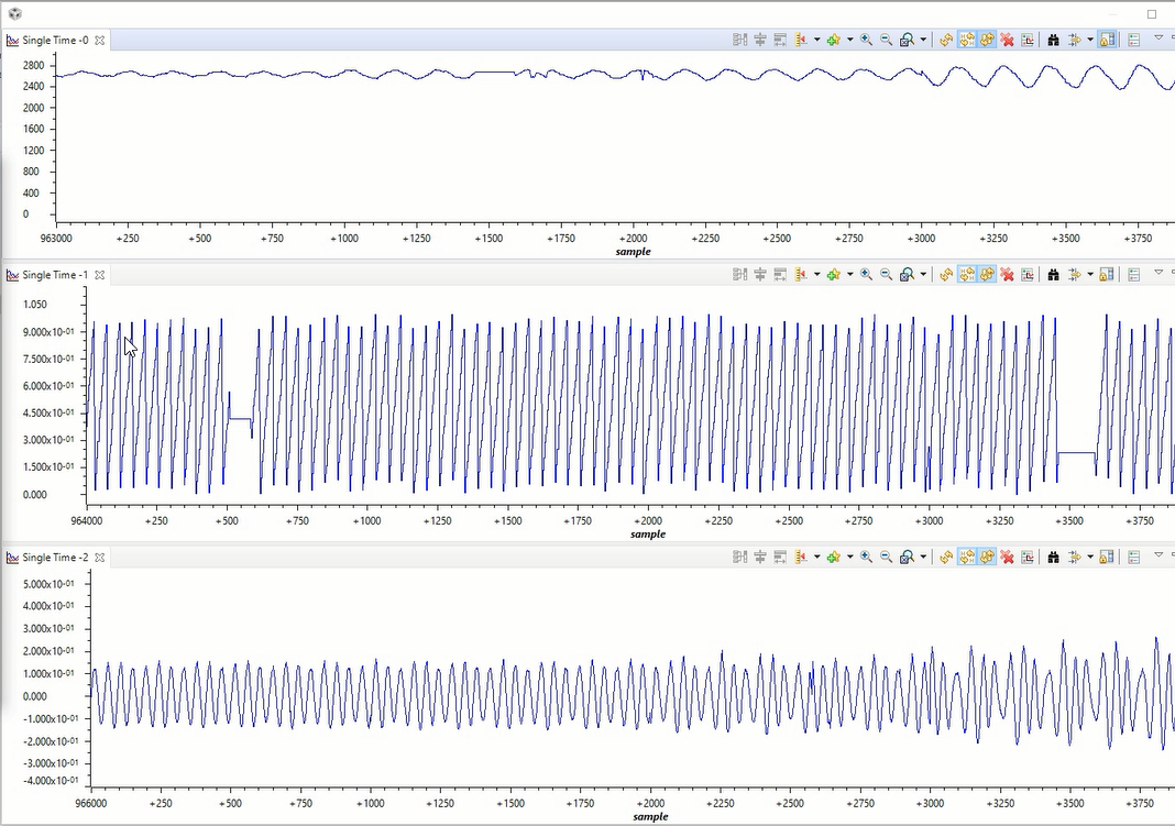
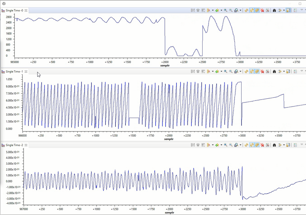
I am working on confidential custom hardware, VFD of 3.7kW rating in which TMS320F28062F is used. Application has been developed using Instaspin labs provided, which is able to run the SPMSM motor without any issue, I am facing problem with the IPMSM type of motor wherein at the particular frequency the motor is vibrating a lot. Let me know if any further specific information is required. Please suggest a solution.

Samir

  • Can you provide a detailed description of your question? What do you mean  "particular frequency"? How much? And any load on the motor? What's the Ld and Lq?

    Did you set the Ld and Lq in user.h seprately according to the motor parameters in its datasheet?

  • Hi Yanming,

    Sure I will provide you with a detailed description. Since I am working on a proprietary project, it would be good if could share your mail ID.

    Regards

    Samir

  • Hi Yanming, waiting for your reply.

    Regards
    Samir

  • Did you try to set the value of Ld and Lq sepratly according to the datasheet of the motor, and see what happens?

    You may request a friendship with me, and then you can just share the message with me.

  • If there is nothing to discuss on the forum, I would rather close the thread. If it is a open question, pls use the forum for the benefit of the forum users

  • It seems like your motor is a very high saliency ratio IPM motor. You have to add a function to implement decoupling the d-axis and q-axis current for such a motor, and you might need to tune the Id reference per the speed and load, not keep the Id always zero that is for SPM. You may try to search for some related papers and to add these two functions.

    For the Id reference control, you might refer to the example lab 13 (MTPA) in motor control SDK, but there is no example for decoupling control.

    C2000WARE-MOTORCONTROL-SDK: http://www.ti.com/tool/C2000WARE-MOTORCONTROL-SDK

  • Dear Yanming

    I am aware of the fact that this one is high saliency motor and MTPA needs to be implemented in order to utilize both the torques magnetic as well as reluctance. So I have already implemented MTPA in my code with the help of SPRACF3 and Lab-13 code. I have attached the code snippet below, but the issue remains the same.

    inline void CTRL_runOnLine_User ( CTRL_Handle handle , const HAL_AdcData_t *pAdcData , HAL_PwmData_t *pPwmData ) {
    CTRL_Obj *obj = (CTRL_Obj *) handle;
    
    _iq angle_pu;
    
    MATH_vec2 phasor;
    
    _iq gIs_mtpa_pu_u = _IQ(0.0);
    _iq gId_mtpa_pu_u = _IQ(0.0);
    _iq gIq_mtpa_pu_u = _IQ(0.0);
    
    // run Clarke transform on current
    CLARKE_run(obj->clarkeHandle_I, &pAdcData->I, CTRL_getIab_in_addr(handle));
    
    // run Clarke transform on voltage
    CLARKE_run(obj->clarkeHandle_V, &pAdcData->V, CTRL_getVab_in_addr(handle));
    
    // run the estimator
    EST_run(obj->estHandle, CTRL_getIab_in_addr(handle), CTRL_getVab_in_addr(handle), pAdcData->dcBus, TRAJ_getIntValue(obj->trajHandle_spd));
    
    // generate the motor electrical angle
    angle_pu = EST_getAngle_pu(obj->estHandle);
    
    // compute the sin/cos phasor
    CTRL_computePhasor(angle_pu, &phasor);
    
    // set the phasor in the Park transform
    PARK_setPhasor(obj->parkHandle, &phasor);
    
    // run the Park transform
    PARK_run(obj->parkHandle, CTRL_getIab_in_addr(handle), CTRL_getIdq_in_addr(handle));
    
    // when appropriate, run the PID speed controller
    if (CTRL_doSpeedCtrl(handle)) {
    _iq refValue = TRAJ_getIntValue(obj->trajHandle_spd);
    _iq fbackValue = EST_getFm_pu(obj->estHandle);
    _iq outMax = TRAJ_getIntValue(obj->trajHandle_spdMax);
    _iq outMin = -outMax;
    
    // reset the speed count
    CTRL_resetCounter_speed(handle);
    
    PID_setMinMax(obj->pidHandle_spd, outMin, outMax);
    
    PID_run_spd(obj->pidHandle_spd, refValue, fbackValue, CTRL_getSpd_out_addr(handle));
    
    #ifdef MTPA
    float gIs_ref_float;
    gIs_ref_float = _IQtoF(_IQmpy( CTRL_getSpd_out_pu(handle), _IQ(USER_IQ_FULL_SCALE_CURRENT_A)));
    
    float g_Flux = obj->motorParams.ratedFlux_VpHz;
    float g_Diff_Lq_Ld = (obj->motorParams.Ls_q_H - obj->motorParams.Ls_d_H);
    float g_Id_Ref = (g_Flux - (float) (sqrt((g_Flux * g_Flux) + (8 * (g_Diff_Lq_Ld * g_Diff_Lq_Ld) * (gIs_ref_float * gIs_ref_float))))) / (4 * g_Diff_Lq_Ld);
    float g_Iq_Ref = (float) (sqrt((gIs_ref_float * gIs_ref_float) - (g_Id_Ref * g_Id_Ref)));
    gId_mtpa_pu_u = _IQ(-g_Id_Ref/USER_IQ_FULL_SCALE_CURRENT_A);
    gIq_mtpa_pu_u = _IQ(g_Iq_Ref/USER_IQ_FULL_SCALE_CURRENT_A);
    #endif
    
    }
    
    // when appropriate, run the PID Id and Iq controllers
    if (CTRL_doCurrentCtrl(handle)) {
    _iq Kp_Id = CTRL_getKp(handle, CTRL_Type_PID_Id);
    _iq Kp_Iq = CTRL_getKp(handle, CTRL_Type_PID_Iq);
    _iq refValue;
    _iq fbackValue;
    _iq outMin, outMax;
    
    // read max voltage vector to set proper limits to current controllers
    _iq maxVsMag = CTRL_getMaxVsMag_pu(handle);
    
    // reset the current count
    CTRL_resetCounter_current(handle);
    
    // ***********************************
    // configure and run the Id controller
    
    // compute the Kp gain
    // Scale Kp instead of output to prevent saturation issues
    if (CTRL_getFlag_enableDcBusComp(handle)) {
    Kp_Id = _IQmpy(Kp_Id, EST_getOneOverDcBus_pu(obj->estHandle));
    }
    
    PID_setKp(obj->pidHandle_Id, Kp_Id);
    
    // compute the reference value
    #ifdef MTPA
    refValue = gId_mtpa_pu_u; //TRAJ_getIntValue(obj->trajHandle_Id) + CTRL_getId_ref_pu(handle);
    #else
    refValue = TRAJ_getIntValue(obj->trajHandle_Id) + CTRL_getId_ref_pu(handle);
    #endif
    
    // update the Id reference value
    EST_updateId_ref_pu(obj->estHandle, &refValue);
    
    // get the feedback value
    fbackValue = CTRL_getId_in_pu(handle);
    
    // set minimum and maximum for Id controller output
    outMax = maxVsMag;
    outMin = -outMax;
    
    // set the minimum and maximum values
    PID_setMinMax(obj->pidHandle_Id, outMin, outMax);
    
    // run the Id PID controller
    PID_run(obj->pidHandle_Id, refValue, fbackValue, CTRL_getVd_out_addr(handle));
    
    // ***********************************
    // configure and run the Iq controller
    
    // compute the Kp gain
    // Scale Kp instead of output to prevent saturation issues
    if (CTRL_getFlag_enableDcBusComp(handle)) {
    Kp_Iq = _IQmpy(Kp_Iq, EST_getOneOverDcBus_pu(obj->estHandle));
    }
    
    PID_setKp(obj->pidHandle_Iq, Kp_Iq);
    
    // get the reference value
    if (CTRL_getFlag_enableSpeedCtrl(handle)) {
    #ifdef MTPA
    refValue = gIq_mtpa_pu_u;
    #else
    refValue = CTRL_getSpd_out_pu(handle);
    #endif
    
    }
    else {
    // get the Iq reference value
    refValue = CTRL_getIq_ref_pu(handle);
    }
    
    // get the feedback value
    fbackValue = CTRL_getIq_in_pu(handle);
    
    // set minimum and maximum for Id controller output
    outMax = _IQsqrt(_IQmpy(maxVsMag,maxVsMag) - _IQmpy(CTRL_getVd_out_pu(handle),CTRL_getVd_out_pu(handle)));
    outMin = -outMax;
    
    // set the minimum and maximum values
    PID_setMinMax(obj->pidHandle_Iq, outMin, outMax);
    
    // run the Iq PID controller
    PID_run(obj->pidHandle_Iq, refValue, fbackValue, CTRL_getVq_out_addr(handle));
    }
    
    {
    _iq angleComp_pu;
    
    // compensate angle delay
    angleComp_pu = CTRL_angleDelayComp(handle, angle_pu);
    
    // compute the sin/cos phasor
    CTRL_computePhasor(angleComp_pu, &phasor);
    }
    
    // set the phasor in the inverse Park transform
    IPARK_setPhasor(obj->iparkHandle, &phasor);
    
    // run the inverse Park module
    IPARK_run(obj->iparkHandle, CTRL_getVdq_out_addr(handle), CTRL_getVab_out_addr(handle));
    
    // run the space Vector Generator (SVGEN) module
    SVGEN_run(obj->svgenHandle, CTRL_getVab_out_addr(handle), &(pPwmData->Tabc));
    
    return;
    } // end of CTRL_runOnLine_User() function


    Thanks and Regards
    Samir

  • Could you please post some phase current waveforms of the motor to show the problem? What speed is the motor running at? And any load on the motor?

    Did you try to use the graph tool with datalog to check the rotor angle and feedback speed? If not, you may refer to the lab01b and lab01c to use this graph tool.

    Did you try to use the TI EVM board to identify and run the motor if possible? And compare the testing result with your own board? Please make sure that the current and voltage sensing signals are good enough on your own board.

  • Hi Yanming,

    Thanks for all the suggestions.

    I have tried plotting feedback-speed (single time-0), feedback-angle (single time-1) and motor-current (single time-2) in the graph tool using datalog method as suggested within Lab-1b. Below is the code implementation.

    Have defined the buffer in main.c itself

    #define DATA_LOG_SIZE 1000

    uint16_t datalogbuff0[DATA_LOG_SIZE];
    float datalogbuff1[DATA_LOG_SIZE];
    float datalogbuff2[DATA_LOG_SIZE];

    #pragma DATA_SECTION(datalogbuff0,"graph_data");
    #pragma DATA_SECTION(datalogbuff1,"graph_data");
    #pragma DATA_SECTION(datalogbuff2,"graph_data");

    In the mainISR

    datalogbuff0[cntr] = (uint16_t)(_IQtoF(gMotorVars.Speed_krpm)*1000);
    datalogbuff1[cntr] = _IQtoF(gMotorVars.est_angle_pu);
    datalogbuff2[cntr] = _IQtoF(gAdcData.I.value[0]);

    Also, I have attached the video of the graph tool while running in debug mode. In the video you will see, custom GUI is being used to command reference speed, which is also being used for monitoring few parameters. In the beginning, the motor is started at 80Hz and later on frequency is increased in steps of 2 to 5Hz. At around 88Hz motor vibrates and stop (at time 01:48 in the video). From the graph data you can observe that at this frequency, motor current amplitude starts oscillating, hence the ripples in feedback-speed increases.

    Click here to play this video

    Here are direct responses to your queries

    Could you please post some phase current waveforms of the motor to show the problem? What speed is the motor running at? And any load on the motor?
    You will find the current waveform in the video, Single Time-2 tab is used for output current. Till 88Hz motor runs fine. The motor is connected to the submersible pump.

    Did you try to use the graph tool with datalog to check the rotor angle and feedback speed? If not, you may refer to the lab01b and lab01c to use this graph tool.
    Yes, video is attached.

    Did you try to use the TI EVM board to identify and run the motor if possible? And compare the testing result with your own board? Please make sure that the current and voltage sensing signals are good enough on your own board.
    No, I haven't used any EVM board so far to run or identify the motor. Current and voltage sensing is good. Because with the same drive I am able to run the SPM motor with a similar power rating, up to 120Hz, 3.8Kw, 8.5A.

    Let me know if any other data is needed.

    Thanks and regards

    Samir

  • Hi Samir,

    Could you please post some captured current waveform directly since the Video can't be supported? Did you have the inductance vs. current curve of the motor? If not, you might ask for this data from the motor manufacturer to see if the inductance changes a lot with the increasing current. If yes, you have to change the motor parameters on the fly according to the spec. of the motor as the lab13 in MCSDK. The inductance table in lab13 is just for reference, you should set the inductance table based on the spec. of the motor.

    Did you meet the vibration during the motor is tested with a full load? Or without loading at the motor is just connected to the pump?

  • Hi Yanming

    Could you please post some captured current waveform directly since the Video can't be supported? 
     Am attaching the video in another format. Also attaching the screenshots of the video, in case if this time also the video doesn't work.

    1: 

    2:

    3:

    Video:

    Did you have the inductance vs. current curve of the motor?
    No, I don't have the Inductances Vs Current data right now. I have asked the manufacturer to provide the same. WIll share with you once I have it.

    If not, you might ask for this data from the motor manufacturer to see if the inductance changes a lot with the increasing current. If yes, you have to change the motor parameters on the fly according to the spec. of the motor as the lab13 in MCSDK. The inductance table in lab13 is just for reference, you should set the inductance table based on the spec. of the motor.
    What do you mean by lot here? How much variation is allowed?

    Did you meet the vibration during the motor is tested with a full load? Or without loading at the motor is just connected to the pump?
    Vibrations are there in all the three situations i.e only motor without pump, with pump but without load and with the pump on full load. But in each case, the frequency threshold at which vibration starts is different, till this threshold frequency there is negligible vibration in all the cases.

    Regards

    Samir

  • I don't think the rotor angle in the figure above is correct. You might try to use a lower Kp&Ki of the speed PI controller for the high speed, and tune the current controller as well.

    Did you have the detailed specification of the motor? What is the rated frequency, current, and voltage of the motor?

    Is it possible to increase the dc bus voltage to run the motor at the same frequency and load to see what happens? And please check if the "gMotorVars.Vs" equal or close to the USER_MAX_VS_MAG_PU.

    // read Vd and Vq vectors per units
    gMotorVars.Vd = CTRL_getVd_out_pu(ctrlHandle);
    gMotorVars.Vq = CTRL_getVq_out_pu(ctrlHandle);

    // calculate vector Vs in per units
    gMotorVars.Vs = _IQsqrt(_IQmpy(gMotorVars.Vd, gMotorVars.Vd) + _IQmpy(gMotorVars.Vq, gMotorVars.Vq));

  • Hi Samir,

    We'd like to close this thread first since the question will be discussed in chat. Please create a new thread if you have any other questions. Thanks!