This thread has been locked.

If you have a related question, please click the "Ask a related question" button in the top right corner. The newly created question will be automatically linked to this question.

TMS320F28065: ePWM updown config

Part Number: TMS320F28065

Hi,

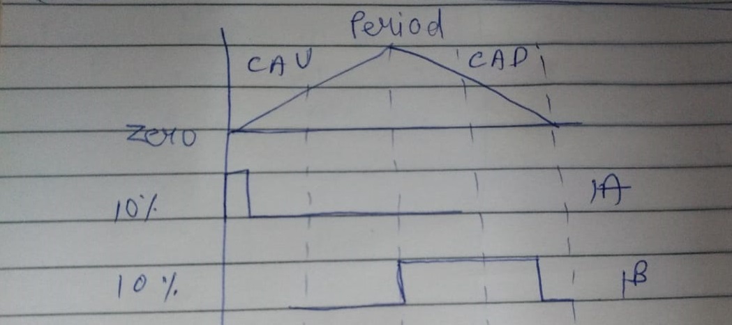
I wanted to generate 2 pulses from ePWM 1A and 1B. 1A sets at zero and clears at CAU, 1B sets at PRD and clears at CAD. Im unable to get required. Please let me know if its possible.

currently used config:

EPwm1Regs.TBPRD = 3000; //  15kHz
EPwm1Regs.TBPHS.half.TBPHS = 0x0000; 
EPwm1Regs.TBCTR = 0x0000;

EPwm1Regs.TBCTL.bit.CTRMODE = TB_COUNT_UPDOWN; 

EPwm1Regs.TBCTL.bit.PHSEN = TB_DISABLE; 
EPwm1Regs.TBCTL.bit.HSPCLKDIV = TB_DIV1; 
EPwm1Regs.TBCTL.bit.CLKDIV = TB_DIV1;

EPwm1Regs.CMPCTL.bit.SHDWAMODE = CC_SHADOW; 
EPwm1Regs.CMPCTL.bit.SHDWBMODE = CC_SHADOW;
EPwm1Regs.CMPCTL.bit.LOADAMODE = CC_CTR_ZERO;
EPwm1Regs.CMPCTL.bit.LOADBMODE = CC_CTR_ZERO;

EPwm1Regs.CMPA.half.CMPA = 2000; // can be varied

EPwm1Regs.AQCTLA.bit.ZRO = AQ_SET; 
EPwm1Regs.AQCTLA.bit.CAU = AQ_CLEAR; 

EPwm1Regs.AQCTLB.bit.PRD = AQ_SET; 
EPwm1Regs.AQCTLB.bit.CBD = AQ_CLEAR;

  • Hi Ravi,

    This should be very possible. May you please describe the waveform you are currently getting or describe what you mean by "Im unable to get required"?

    The configuration you have looks good expect for the following line: 

    EPwm1Regs.AQCTLB.bit.CBD = AQ_CLEAR;

    This should instead be:

    EPwm1Regs.AQCTLB.bit.CAD = AQ_CLEAR;

    Best Regards,

    Marlyn

  • Madam,

    I have tried 

    Pwm1Regs.AQCTLB.bit.CAD = AQ_CLEAR;

    The issue faced is Im getting:

    The need is to get 1A and 1B of the same pos duty. 

  • Hi Ravi,

    To get the same positive duty cycle you can use a CMPA and CMPB value.

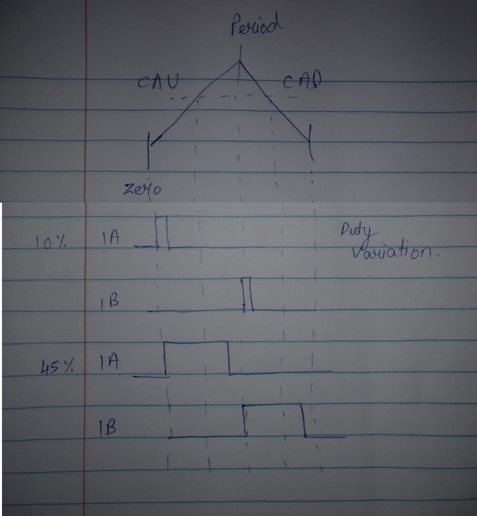
    Configure CMPA for the desired duty cycle you want. In your example you would like 10% positive duty cycle and your TBPRD value is 3000 so you need a CMPA value of 600.

    Set the CMPB value to be TBPRD-CMPA (3000-600=2400)

    Then you can use the configuration below to set the desired actions: 

    EPwm1Regs.AQCTLA.bit.ZRO = AQ_SET;    
    EPwm1Regs.AQCTLA.bit.CAU = AQ_CLEAR;  
    
    EPwm1Regs.AQCTLB.bit.PRD = AQ_SET;    
    EPwm1Regs.AQCTLB.bit.CBD = AQ_CLEAR;  

    Best Regards,

    Marlyn

  • Madam,

    I have tried with the below settings:

    CMPA value of 600. (using a variable to change CMPA & CMPB in debug)

    Set the CMPB value to be TBPRD-CMPA (3000-600=2400) (tried TBPRD-CMPA)

    Still was getting uneven pos duty on 1A and 1B. 

    Wanted to know if Im missing any other settings.

  • Ravi,

    Do you have a way of measuring what the actual positive duty value is for both PWM1A and PWM1B that you are observing?

    Are you dynamically changing the value of CMPA and CMPB? If so, lets try isolating the issue for now and just focusing on matching 10% pos duty for both outputs.

    This is the code I have in my c file and I can see 10% pos duty on both A/B outputs. Please try to run this version on your platform.:

    void main(void)
    {
        //
        // Step 1. Initialize System Control:
        // PLL, WatchDog, enable Peripheral Clocks
        //
        InitSysCtrl();
    
        //
        // Init GPIO pins for ePWM1
        //
        InitEPwm1Gpio();
    
        //
        // Initialize the ePWM
        //
        EALLOW;
        SysCtrlRegs.PCLKCR0.bit.TBCLKSYNC = 0;
        EDIS;
    
        InitEPwm1Example();
    
        EALLOW;
        SysCtrlRegs.PCLKCR0.bit.TBCLKSYNC = 1;
        EDIS;
    
        for(;;)
        {
            __asm("          NOP");
        }
    }
    
    void
    InitEPwm1Example()
    {
        //
        // Setup TBCLK
        //
        EPwm1Regs.TBPRD = 3000;                  // Set timer period
        EPwm1Regs.TBPHS.half.TBPHS = 0x0000;     // Phase is 0
        EPwm1Regs.TBCTR = 0x0000;                // Clear counter
    
        //
        // Set Compare values
        //
        EPwm1Regs.CMPA.half.CMPA = 600;     // Set compare A value
        EPwm1Regs.CMPB= 2400;               // Set Compare B value
    
        //
        // Setup counter mode
        //
        EPwm1Regs.TBCTL.bit.CTRMODE = TB_COUNT_UPDOWN; // Count up down
        EPwm1Regs.TBCTL.bit.PHSEN = TB_DISABLE;        // Disable phase loading
        EPwm1Regs.TBCTL.bit.HSPCLKDIV = TB_DIV1;       // Clock ratio to SYSCLKOUT
        EPwm1Regs.TBCTL.bit.CLKDIV = TB_DIV1;
    
        //
        // Setup shadowing
        //
        EPwm1Regs.CMPCTL.bit.SHDWAMODE = CC_SHADOW;
        EPwm1Regs.CMPCTL.bit.SHDWBMODE = CC_SHADOW;
        EPwm1Regs.CMPCTL.bit.LOADAMODE = CC_CTR_ZERO;  // Load on Zero
        EPwm1Regs.CMPCTL.bit.LOADBMODE = CC_CTR_ZERO;
    
        //
        // Set actions
        //
        EPwm1Regs.AQCTLA.bit.ZRO = AQ_SET;    // Set PWM1A on event A, zero
        EPwm1Regs.AQCTLA.bit.CAU = AQ_CLEAR;  // Clear PWM1A on event A, up count
    
        EPwm1Regs.AQCTLB.bit.PRD = AQ_SET;    // Set PWM1B on event A, period
        EPwm1Regs.AQCTLB.bit.CBD = AQ_CLEAR;  // Clear PWM1B on event B, down count
    }

    Best Regards,

    Marlyn