

Other Parts Discussed in Thread: TMS320F280025C, TMS320F280049C
Dear team:
One of my customers has questions about the PWM interrupt in the routine “HVPSFB_PCMC”. The details are as follows:
He drew the PWM sequence diagram according to the routine, as follows:
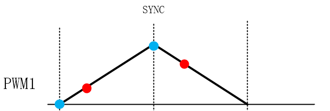
Red is the approximate time of triggering PWM interrupt, and blue is 0 and PRD respectively, which is used to generate synchronous signal.
In the routine, the CMPB value of EPWM1 is used to generate the synchronization signal:
(*ePWM[n]).TBCTL.bit.SYNCOSEL = TB_CTR_CMPB;
The routine writes CMPB=0 in the rising interrupt, but the synchronizing signal has not been generated yet and entering the falling interrupt. Change CMPB to prd. Doesn't this mean that the synchronizing signal has not been generated?
If the program doesn't need the synchronization signal, then just set it to not generate the synchronization signal. Why do you need to change the value of CMPB back and forth?
Best regards
