This thread has been locked.

If you have a related question, please click the "Ask a related question" button in the top right corner. The newly created question will be automatically linked to this question.

TMS320F280025C: Problems of starting DMA from LIN/SCI module

Part Number: TMS320F280025C

Dear team:

One of my customer reference routines(lin_ex3_sci_dma) configures the Lin module for SCI use. In the example, the multi buffering mode is used and needs to be modified to disable the multi buffering mode. However, after changing to disable multi buffer mode, SCI cannot start DMA. What might be the problem? Here's where he changed the code:

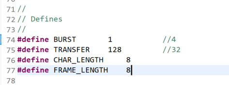
1. Main program definition:

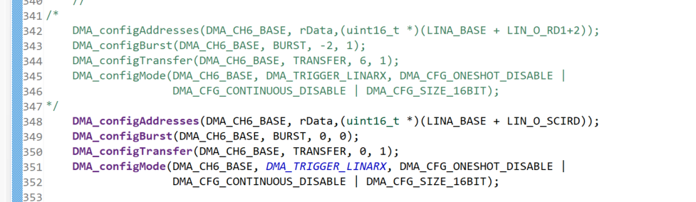
2. Modify the DMA initialization function initdma():


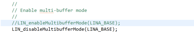
3. Modify the Lin / SCI configuration function configurescimode (void):


4. Operation results:

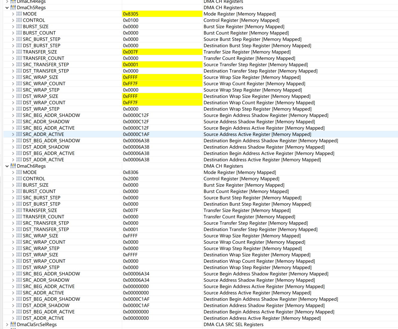
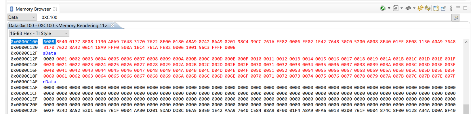
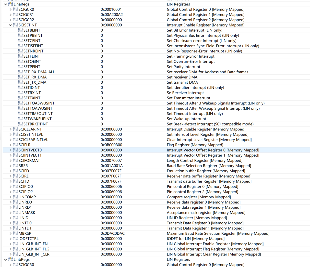
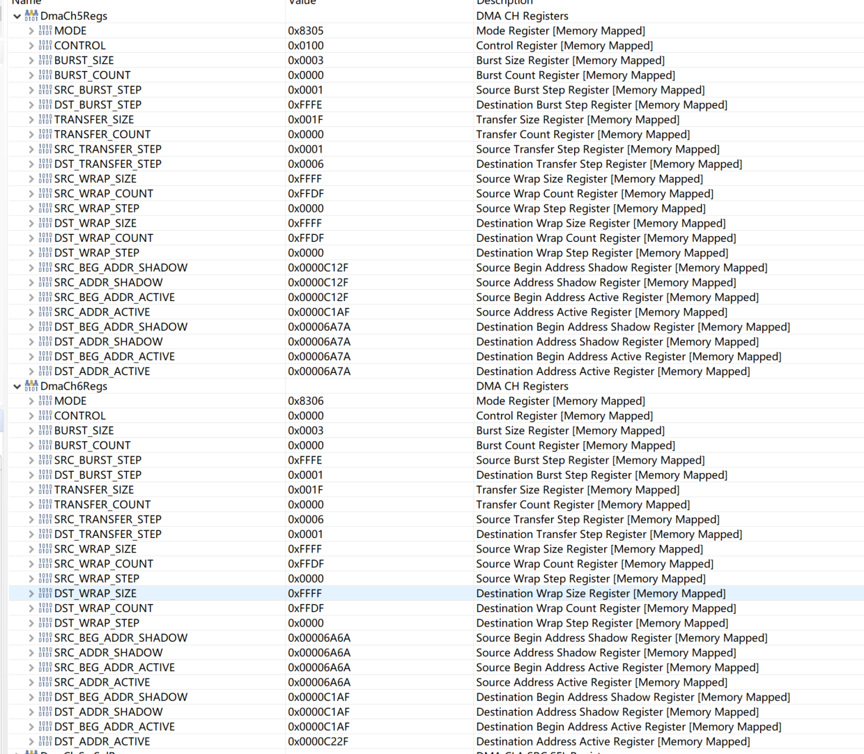
Observing the SCITD and SCIRD of LIN, the data is the same, both are 7FH. Therefore, LIN / SCI works normally. The destination address and source address of DMACH6 are not activated, indicating that DMACH6 has not received RX_DMA signal. Observe SET_RX_DMA and SET_TX_DMA in SCISETINT of LIN, both of them are 0. This part has not been modified, and the original sample program is the same. The running results of the original sample program are attached:

In addition, are there any errors in the technical manual?

The LIN register address given in SPRUIN7 is as follows:

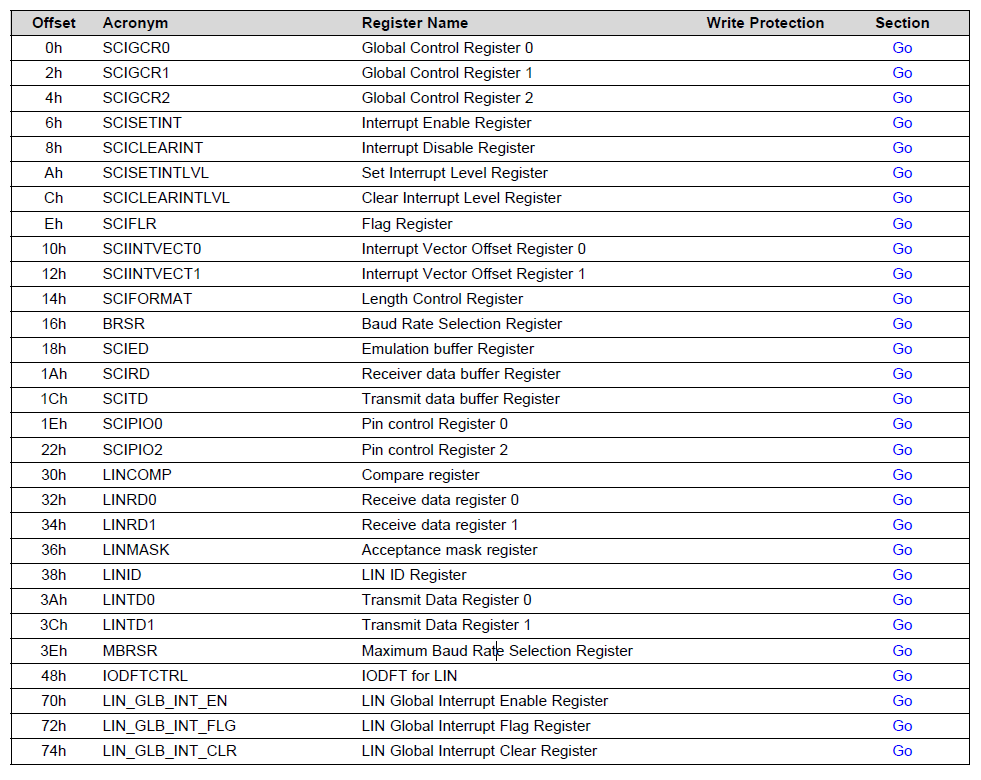
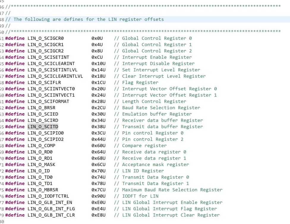
The address defined in driverlib is as follows:

Best regards

  • Hi,

    Let me go through the details that you have captured, and will respond to you within a day or two.

    Yes, the TRM offset address needs to be fixed and has to match driverlib header file offset address. I will submit a ticket to do so in the next release version.

    Best Regards,

    Nirav

  • Hi Nirav:

    Is there any progress on the questions in this post?

    Best regards

  • Hi Green - We are still looking into it, should have an answer for you in next couple of days. Apologize for the delay.

    Best Regards,

    Nirav

  • Hi Nirav:

    Thank you for your continuous attention and look forward to your test results.

  • Hi Green,

    I looked at the register dump that you provided, and it looks like SCISETINT.SET_RX_DMA and SCISETINT_SET_TX_DMA bits are not being set. If you go through the below section in TRM it states that SET_RX_DMA and SET_TX_DMA bits needs to be set if multi-buffer mode is disabled. Can you please try be setting these bits, hopefully that should resolve the issue.

    24.2.4.1.1 Receiving Data in Single-Buffer Mode

    Single-buffer mode is selected when the MBUF MODE bit in SCIGCR1 is cleared to 0. In this mode, SCI sets the RXRDY bit when it transfers newly received data from SCIRXSHF to SCIRD. The SCI clears the RXRDY bit after the new data in SCIRD has been read. Also, as data is transferred from SCIRXSHF to SCIRD, the SCI sets the FE, OE, or PE flags if any of these error conditions were detected in the received data. These error conditions are supported with configurable interrupt capability. The wake-up and break-detect status bits are also set if one of these errors occurs, but they do not necessarily occur at the same time that new data is being loaded into SCIRD. You can receive data by: 1. Polling Receive Ready Flag 2. Receive Interrupt 3. DMA In polling method, software can poll for the RXRDY bit and read the data from the SCIRD register once the RXRDY bit is set high. The CPU is unnecessarily overloaded by selecting the polling method. To avoid this, you can use either the interrupt or DMA method. To use the interrupt method, the SET RX INT bit is set. To use the Local Interconnect Network (LIN) DMA method, the SET RX DMA bit is set. Either an interrupt or a DMA request is generated the moment the RXRDY bit is set

    24.2.4.2.1 Transmitting Data in Single-Buffer Mode

    Single-buffer mode is selected when the MBUF MODE bit in SCIGCR1 is cleared to 0. In this mode, SCI waits for data to be written to SCITD, transfers it to SCITXSHF, and transmits the data. The TXRDY and TX EMPTY bits indicate the status of the transmit buffers. That is, when the transmitter is ready for data to be written to SCITD, the TXRDY bit is set. Additionally, if both SCITD and SCITXSHF are empty, then the TX EMPTY bit is also set. You can transmit data by: 1. Polling Transmit Ready Flag 2. Transmit Interrupt 3. DMA In polling method, software can poll for the TXRDY bit to go high before writing the data to the SCITD register. The CPU is unnecessarily overloaded by selecting the polling method. To avoid this, you can use the interrupt or DMA method. To use the interrupt method, the SET TX INT bit is set. To use the DMA method, the SET TX DMA bit is set. Either an interrupt or a DMA request is generated the moment the TXRDY bit is set. When the SCI has completed transmission of all pending frames, the SCITXSHF register and SCITD are empty, the TXRDY bit is set, and an interrupt/DMA request is generated, if enabled. Because all data has been transmitted, the interrupt/DMA request should be halted. This can either be done by disabling the transmit interrupt (CLR TX INT) / DMA request (CLR TX DMA bit), or by disabling the transmitter (clear TXENA bit).

    Best Regards,

    Nirav