This thread has been locked.

If you have a related question, please click the "Ask a related question" button in the top right corner. The newly created question will be automatically linked to this question.

LAUNCHXL-F280049C: Cogging rotor no acceleration speed SDK Lab05

Guru 54057 points
Part Number: LAUNCHXL-F280049C
Other Parts Discussed in Thread: DRV8320, BOOSTXL-DRV8320RS, EK-TM4C1294XL, INA240, OPA2350, TMDXIDDK379D, , UCC27714, TIDA-00778, MOTORWARE, DRV8301, TMS320F28027F, DRV8305

Hello all, 

I recently design 22 pole PM rotor out of scrap parts to use on 24 tooth custom stator, 300mΩ  each of 3 phases Star winding. Rotor has some minor cogging but easily rotates over each slot by hand push, initial slot being the hardest. Oddly 6 step trapezoidal FOC sensorless open commutation controller only rock rotor +/-5° 1A up to >8A , 40v to 170v. This cogging torque is well known in RC car groups as delay startup and the KV controllers somehow overcome cogging. Yet FEM analysis without stator skew show cogging torque roughly +/-400-600mNm and we know adding any slot skew reduce that even more.

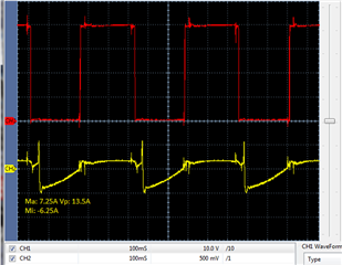
Will space vector FAST and SDK motion spin or even push most typical RC cogging rotor over the first slot? Oddly the non-powered scope capture of two phases is not single sine wave and more of a stepped sinusoidal pattern, perhaps due to the laminations skew angle that changes nearly every 60°. I would classify motor as 22 pole BLDC since SPM has pure sinusoidal wave form when human hand rotates rotor.  

  • Did you have any comparison testing waveforms between FAST and a position sensor for this motor? That could help us to understand your question.  Or posted some tested pictures with the angle and current, 

  • Hello Yanming,

    Yanming Luo said:
    Did you have any comparison testing waveforms between FAST and a position sensor for this motor?

    No I have not tried FAST yet and figured FE would know about cogging rotor startup issues with FAST estimator. Competition clarify cogging (hesitation / kick back) startup aspect is easily overcome with their FOC rotor position control logic. Motor as is has no sensors to monitor position. Will post an EMF capture later today if FAST fails to get past first stator slot.

    My test DC inverter requires small EMF circuit modification to make work with FAST and change of TI launch pads.

  • Yanming like to share (PM) video link (MSOneDrive) issue lab05 spin rotor via FAST estimator <2° either direction, 40vdc 9A or 24vdc 14.6A peak. Several runs of user.h current values produce similar results. Open loop commutation try to switch pole pairs to rapidly, well before rotor cross over 1st stator slot. 

    There is no measurable angle if the rotor ain't moving more than few degrees. 


  • I back step to test 6 pole SPM Lab05. Issue occurs EST_ONLINE speed control does not work after motor was identified. The only change I make seems was typo SDK V2.01/V3.0, stator resistance was input for inductance parameter, shown below.

    Was that a typo bug or intentional and how can that not allow closed loop speed trajectory to change? The net result of no closed loop speed control, torque goes extremely high (75Nm), very slow shaft rotation 1Hz it seems and no change in acceleration after entering higher Hz speed parameter in CCS debug java script.

      Edit: This bug change has no effect on speed controller fixed in SDK V3.01.00.00

    Another possible bug contrary to user.h motor parameters.
                if( (EST_isMotorIdentified(estHandle) == true) &&
                    (state == EST_TRAJ_STATE_ONLINE))
                {
                    float32_t  speed_min_Hz = -USER_MOTOR_FREQ_MIN_HZ; //was ~MAX_HZ
                    float32_t  speed_max_Hz =  USER_MOTOR_FREQ_MAX_HZ;
                    float32_t  speed_maxDelta_Hz = motorVars.speedRef_Hz /
                                                   userParams.trajFreq_Hz;
    
                    // setup the spd trajectory
                    EST_setMinValue_spd_Hz(estHandle, speed_min_Hz);
                    EST_setMaxValue_spd_Hz(estHandle, speed_max_Hz);
                    EST_setMaxDelta_spd_Hz(estHandle, speed_maxDelta_Hz);
                }
            }

  • Copy of debug screen and user.h. Motor is Nidec 6/8 pole 10KRPM 20vdc 1.2A, 18W. What seems out of place?

    /cfs-file/__key/communityserver-discussions-components-files/171/7266.user.h

  • Part of the locked rotor shaft and very high Nm torque stems from Forced Angle not being auto enabled by Lab05 EST_STATE_ONLINE. The code snip below monitors <1Hz rotor speed to first enable force angle and disable >1Hz.

  • Lab05 is for motor parameters identification, please try to run the lab07 with the identified parameters.

    It seems like the motor was not identified correctly, the value of the "motorVars.flux_VpHz" you showed above is a very abnormal number for a low voltage motor. Could you please identify the motor again using lab05 wihtout load?

  • Yanming Luo said:
    Could you please identify the motor again using lab05 wihtout load?

    Motor was without load. The VpHz value is different each time ID runs, sometimes is close to DC supply values. Torque value is way to high during forced angle unless you want to drive screws through 2x4's <1Hz 75Nm is amazingly strong force little current was required 24v.

    Oddly with DRV8320RS we could accelerate the rotor with speed PI control Lab05 after motor ID was complete. So this explains why our very large SPMM would not accelerate either via same custom inverter connected to LaunchXL-49c header pins after DRV8320 symbols/*.c files removed from build to disable it.

    Yanming Luo said:
    "motorVars.flux_VpHz" you showed above is a very abnormal number for a low voltage motor.

    What value would be expected and what function *.c creates this value so we know what circuit to troubleshoot? Also reduced 100nf VSEN-A-C cutoff filters to roughly 40nF, 100pF parallel with 39nF. That made little difference in flux values being returned.

    Also notice VSF timer interrupt is disabled (hal.c) but note suggests it might be needed?

    #ifdef _VSF_EN_
        // enable the cpu timer 0 interrupt for FAST estimator
        Interrupt_enable(INT_TIMER0);
    #endif  // _VSF_EN_


  • Same speed issue Lab07 large torque virtually no velocity other than forced angle SW control allow <1Hz shaft movement.

  • And the exact opposite when Nidec motor current is lower <1A the torque, VpHz are more respectable but motor then goes crazy jumping all over the place. I then put the other TM4C1294 launch pad back to this inverter and easily started the motor 6 and 8 poles six step commutation.

    So it seems the INA240A1 gain 20 is not consistent with PGA gain 12 as the x49c ADC scale factor of RDK is likely not the same. Yet even with lower torque the Fast estimator was not producing the correct startup quadrature. 

  • Which boards are you using? Your own board? If yes, please show the user,h, current, and voltage sensing circuit to understand your questions. As mentioned above, it seems like you didn't identify the motor successfully to get the correct motor parameters for running the motor.

    The #ifdef _VSF_EN_ is only used in lab12 for online changing the PWM frequency in some special applications.

  • It was my test DC inverter with short jumper wires to launch pad configured for SPV filters on Vd/Id pins. The inductance values were all over the place and torque would either be very high or acceptable but no acceleration after 20Khz modulation. Note SDK v3.1 user.h drv8320rs kit has 40Khz default modulation and incorrect bizarre notes about frequency. 

  • Follow up observations for Nidec N25H575 series SPMM:

    With BoostXL-8320 Nidec user.h set for 4 pole pairs notice couple things that differ. The R/L impedance is 1/2 that of typical DC inverter and VpHz remained very low along with Torque values. Perhaps 6" jumper wires add to much capacitance and the FAST estimator works best via PGA gain 12. The INA240A1 gain 20 seems to overdrive the torque likely due to 357Khz BW of the differential amplifier.

  • Did you try to run and identify the motor with TI EVM kits like a luanchPad +boostxlpak? If the motor can run and identify successfully, the issue could be from current and voltage sensing signals on your inverter board. You might try to do this if possible. 

  • Yanming Luo said:
    Did you try to run and identify the motor with TI EVM kits like a luanchPad +boostxlpak?

    That being my last few posted points after switching launchXL to use BoostXL-drv8320rs. Online frequency conversion calculators indicate Nidec motor was running 24000 RPM at 400Hz, seems doubtful.

    The first custom inverter circuits are typical outlined in SPRUHJ1H–January 2013–Revised June 2019. And they also work with EMF capacitor change 100pF on EK-TM4C1294XL launch pad to 39nF LauchXL-TMS280049c. Perhaps the jumper wires add to much capacitance for FAST estimator or higher RDS on resistance NFETS (13mohm) producing large span spurattic ID results?

  • The 39nF capacitor should be on the inverter board (boost-pak board), not on the launch-pad board, and the  EK-TM4C1294XL launch pad doesn't support instaspin-foc.

    What's the target frequency you set to run the motor? And what's the running frequency of the motor if you use an oscilloscope with a current probe to measure the phase current of the motor?

  • The 39nF capacitor should be on the inverter board (boost-pak board), not on the launch-pad board, and the  EK-TM4C1294XL launch pad doesn't support instaspin-foc.

    They 39nF are on the inverter and the cutoff filters for INA240 filters were on lauchXL pad filter pads (R19 C32), (R22 C33), (R25 C34). The EK launch pad drives same inverter via 6 step trapezoidal FOC commutation. Point being the inverter PWM drives and ADC sensor paths work. 

    And what's the running frequency of the motor if you use an oscilloscope with a current probe to measure the phase current of the motor?

    20Hz target would always be reached (20Khz) yet the current parameter made little to no difference other than torque value being lower, Nidec25 would not accelerate after ID.  The rated current being 1.2A  and current probe was very close to adcData.I_A.value watch via scale factor in user.h. Oddly the roll off of the PGA input filers calculates 282ns just above ACQPS=14 (S+H) 280ns via ADCCLK 50Mhz. Later changed 2200pF to 1000pF on the current filters and motorVars.torque_Nm value was more respectable most runs. It seems like a higher bit level acquisition occurred now I think about it. sort of makes sense the PGA's being roughly 1/2 the gain. Curious to know the band width of the PGA's?

  • There is no INA240 on the F280049x launchPad, Which kits are you working on? Could you give a detailed description of the operation steps about how to run/identify the motor on the TI EVM kits? All of the labs in motor control SDK have been validated on the related kits, I don't think the ADC configuration is the root cause as you mentioned above if you are using the C2000 kits.

  • There is no INA240 on the F280049x launchPad, Which kits are you working on?

    Case being lab05 motor ID will be used in production on custom inverters for each motor, those in the same lot. The point of testing a launch pad with a customers DC inverter may allow higher DC voltages a booster pack does not support for the MCU migration path. Why should a customer justify expense and time to design a custom PCB when the EVM has not been proven to run a custom motor design at the same speed or greater than 6 step FOC currently using INA240 current monitors?

    The entire concept of launch pads booster headers severs more than just TI booster packs. That was specifically noted a reason why to choose TI launch pads for development. Seeing is believing and so far the BoostXL-drv8320rs only drive my custom motor 100Hz or so at 40vdc. Yet our expendable test DC inverter was proven to run same motor 2200 RPM 175vdc using stated TI-EVM and INA240 current monitors, AKA old school method. Only after it was proven did a custom PCB become little to no risk investment.

    I don't think the ADC configuration is the root cause

    It was the Full Scale ADC current parameter not very clear as the INA240 outputs ±1.65v peak signals, gain 20V/V. I believe it is the 240 gain being more the issue since PGA's are 12V/V gain.

  • To simplify the topic, can you have a detailed description of the hardware board you used? Or post a schematic about your board? I can't fully understand what questions do you want to discuss finally.

  • I gave up trying to start experimental cogging motor on either inverter early in this thread. Nidec series 25 motor was then used to weed out issues with my DC test inverter connected to launchXL booster headers, INA240's as current monitors. That is were I suspect gain 20V/V effects the ADC full current scale formula for small and large current motors. I later removed test inverter and put the drv8320rs onto the booster headers flashed lab05 for SPIB control. The test inverter uses industry typical H/L side gate drivers, No SPI controls.

    Point was test inverter would not accelerate any rotor up to the trajectory target or (>1Hz) after lab05 ID process completed and motor was put online with ADC full current scale 62 amps via INA240's, posted user.h file above. Note the torque value was extremely high and lab05 ld/lq values were up and down or not at all.

    Can you elaborate on how PGA gain 12V/V differs the ADC full current scale and RDK when the gain becomes 20V/V? 

  • You might configure the PGA with small gain, or connect the output to ADC pins without using the PGA.

  • Part of the PGA/INA issue seems to be the full scale current setting need to be set roughly 20A higher to arrest motor over current. We determined 2mohm shunt had a peak of 40A, roughly 3.27v peak into the ADC channels. Perhaps issue is due to PGA 7Mhz bandwidth at gain 12, can be set high as 24 gain.

    Why when PGA gain set 12 low does it have any effect on the ADC full scale formula value if the gain made 20 versus 12? Comparing apples to apples may reveal if amplifier gain has any bearing. The odd part is the motor current startup (<1Hz) remained saw tooth like as estimator drove into the trajectory target >Hz.

  • As mentioned above, please post the schematic you used. The final amplified gain depends on the PGA setting gain and external connection resistor. How did you get the 40A peak current value? What USER_ADC_FULL_SCALE_CURRENT_A do you set in user.h based on your hardware?

  • It was INA240A1 had to set 62A full scale user.h when the INA peak output is only 40A. Full scale value need to be roughly 22A> or 62A. Otherwise small motor would burn up as it did to one Nidec and heated 25 series coils. That is why I question the scale formula being consistent when the amplifier gain is >12 via the x49c PGA. The motor SDK was seemingly developed for/with PGA amps only no other external testing.

  • I don't think you need to connect the output of the INA240A1 to PGA, you might use the ADC pins without a PGA connection. It seems like the 62A current scale value is not correct if the shunt resistor is 2mOHM as you mentioned above.

    MotorControl SDK can support both internal PGA or external amplify that is independent of the current sampling circuit. You might refer to the example for the high voltage kit that doesn't use the PGA.

  • I don't think you need to connect the output of the INA240A1 to PGA, you might use the ADC pins without a PGA connection.

    That was the ADC connection to INA but the ADC scale for 20V/V is not the same for PGA 12V/V gain, see my point now? Seemingly It's not the hardware causing the problem rather software. ADC scale factor formula determined for PGA gain does not exactly factor the same for external amp gains >12.

     Why not set the PGA gain 24 if the ADC scale factor has no affect on motor current?

    MotorControl SDK can support both internal PGA or external amplify

    Oddly only PGA amps were/are depicted in SPRUHJ1H–January 2013–Revised June 2019.

  • That just shows how to calculate the current and voltage scale value, and doesn't mean you must use the same sampling circuit.

    It seems like the current or voltage scale value is not correct. The maximum sampling current will be over the ADC range if you use the PGA with 12 or 24. 

  • The maximum sampling current will be over the ADC range if you use the PGA with 12 or 24. 

    Seemingly not true for 1.2 amp motor. Granted value has an effect on low end error % as does amplifier gain. Both need to be factored into the ADC full scale especially for low current motors. That is why all DMM have separate scales for Amps and Milliamp to improve LSB counts with low input signals have less error %. Note 24Nm in above CCS lab05 indicates large ADC error % relative to LSB measures. Seemingly EMF via typical low voltage divider (82k/4k95) would not affect torque readings so much.

    There is more to the point of odd inductance calculations via INA240 400Khz bandwidth. Any idea how the PGA 7Mhz or OPA2350 used in HV kit each maintain accurate ld/lq values in lab05? What is the minimum amplifier bandwidth FAST estimator motor ld/lq can be determined? The community should be warned be aware INA240 if it is found to cause issues with motor ID ld/lq higher error %.

    https://www.ti.com/product/OPA2350

  • Show a picture, post the schematic, and user.h that could help us to understand your questions. I don't think the issue is as you mentioned above. The bandwidth of the PGA and INA240 are good enough for your motor control.

  • The bandwidth of the PGA and INA240 are good enough for your motor control.

    Yet OPA2350 has 38Mhz bandwidth why use such high bandwidth when lower cost lower bandwidth amps are available? Why did TI not use INA240A1 for HV kit as it has built in PWM rejection filter on the front end extremely low temperature drift? It would seem likely 400Khz -3db is not precise enough and R/L RS ohms also has random odd values and rotor torque readings.

    Tina analysis of INA240 2mohm shunt 40A P2P or 80AP , +3.27v ADC peak. Yet setting ADC full scale current >62A seemed to cause CMPSS tripping, for another low inductance motor. I was using the x49c DAC set +1.65v for INA reference. Seemingly the ADC full scale current (user.h) represents Peak value, what has gone wrong? Perhaps INA PWM rejection, gain and bandwidth account for incorrect ADC current measures for FAST estimator to determine correct RsOhms or torque.   Posted the user.h already and PGA gain is 12 by default in SDK so making PGA gain 24 will over current ADC full scale just like the INA gain 20 seems to do. 

  • Insert image URL upload button is missing inside the dialog box again.

  • Generally, the INA240 is used for current sensing with the inline shunt resistor in a low voltage application, its maximum voltage is only 80V. The maximum supporting voltage of the high voltage kit will be 400VDC, and the high voltage kit shows how to implement the shunt current on the low side for motor control. 

    You might refer to the industry kit as the link below if you want to use the inline shunt resistor or insolation current sensing.

    TMDXIDDK379D https://www.ti.com/tool/TMDXIDDK379D

    As replied to you, I don't think you set the correct USER_ADC_FULL_SCALE_CURRENT_A according to your hardware or there is some connection or noise issued for current sensing on your board.

  • Generally, the INA240 is used for current sensing with the inline shunt resistor in a low voltage application, i

    Low side monitors are not prone to high side or inline CMM, so the 80V maximum is/was not an issue.

    As replied to you, I don't think you set the correct USER_ADC_FULL_SCALE_CURRENT_A according to your hardware or there is some connection or noise issued for current sensing on your board.

    I don't think you are grasping the A/V of any shunt resistance is directly proportional to gain and PGA gain setting relative to ADC full scale value in this control comparison. Simply put if we double the input gain of the current sensor the SDK must be adjusted to follow.

    Where is any formula to determine the correct ADC full current value based on amplifier gain?

    Technically USER_ADC_FULL_SCALE_CURRENT_A (ADFS) should be set for 80A Peak based on the shunt A/V*20 gain. That must have seemed excessive to me or caused CMPSS tripping that could not be easily arrested via EPWM blanking configurations. Granted I was pushing the limits on 1.2A motor but not on 50A motor and neither one would accelerate trajectory after ID. The ADFS 80A had to be tweaked downward 62A to compensate for low end precision error. Yet even for 50A motor CMPSS would easily trip OC with 62A ADFS and being reluctant to bump it up to 80A with EPWM CMPSS blanking enabled 50µs offset @20Khz.

    Even with PGA gain 12 and ±42A Peak ADFS, this defaults 21A P2P since boostXL_drv8320rs claims 14A MAX peak with 15A peak trip. I am confused by the lack of concern that AC current wave form has ± half cycles and the word peak seems obscure when gain >12. Current sensors split mid supply rail produce P2P output or 1/2 cycle magnitude, not peak magnitude. Peak phase current sampling requires software algorithm to sample and spit peak magnitude into P2P values of ±2048 counts. For SPV phase parameters store each P2P value and later determine peak if at all used for SPV. It seems the ADFS specifies peak current when P2P current is the real time sensitive wave form being measured and sampled.   

  • Yes, you are correct, the INA240 can be used for the shunt resistor current sensing on the low-side, but the general OPA could be enough and cheaper in most cases.

    I suppose you should have taken a look at chapter 5.2 of the instaspin user's guide (SPRUHJ1H) that has the formula to determine the correct ADC full current value based on amplifier gain.

    The USER_ADC_FULL_SCALE_CURRENT_A defines the maximum current at the input to the AD converter. The value is represented by the maximum ADC input (3.3V) and conversion (0FFFh), and the value is hardware-dependent and should be based on the current sensing and scaling to the ADC input. 

    So the USER_ADC_FULL_SCALE_CURRENT_A = 3.3/(0.002*20)=82.5(A) if you are using 2(mOHM) shunt resistor, INA240 with gain equal to 20, and connect the output of INA240 to an ADC pin without using PGA.

  • So the USER_ADC_FULL_SCALE_CURRENT_A = 3.3/(0.002*20)=82.5(A)

    Yet the INA240A1 clips the output >±40A P2P or 80A peak. The the word (Maximum) does not seem to relate to DC current range as it relates to a sinusoidal wave form expressed as an ADC equivalent magnitude. A 3mohm shunt will improve the ADC scale precision LSB that seems a good solution but the gain 20 is very high, perhaps SNR too.

    I suppose you should have taken a look at chapter 5.2 of the instaspin user's guide (SPRUHJ1H) that has the formula to determine the correct ADC full current value based on amplifier gain.

    Perhaps in another chapter it discusses PGA gain in a formula but 5.2.1 omits any discussion of gain being factored into the ADC full scale range. Mentions the word gain in the title then drops the ball. Notice the example uses 10mohm shunt, surely LSB will have better low end precision than 2mohm.

  • The USER_ADC_FULL_SCALE_CURRENT_A defines the maximum current at the input to the AD converter.

    This may be where confusion begins since the OP output bias level is +1.65v and half the ADC full scale Peak or 2048 (0x800) counts. The sensors signal is peak to peak rated (P2P) divided by a bias voltage +1.65v. Seemingly the ADC full scale is a Peak value as it relates to motor current measure. Also AC current negative half cycle does not add to power formula watts. According to several sources negative amps are treated as a positive or mirror value in ohms law P=EI..  

  • Sorry for confusing you, please follow the formula mentioned above to calculate the SER_ADC_FULL_SCALE_CURRENT_A which is the maximum sampling current of ADC and is related to the FAST algorithm.

  • I apologize for length of this post and extended questioning, most my experience has been with high voltage low current SPM motors.

    Seemingly there is low end shunt/amp error occurring required 20% reduction in the ADC full scale value. Agree amp gain should not be a great concern other than shunt value error % in any amp gain. That 20% low end shunt error affects the low end of the ADFS in a bad way. Oddly error % mandated 62A versus 82.5A reduced scaling ADFS.

    The INA amp 2mohm shunt outputs 40mV/A however the floor of the signal is roughly 40mV above ground rail, so the first 1A=80mV above ADC channel offsets. I can understand for low end current setting ADFS 62A to account for 20% low end error. Yet motors with low inductance windings had similar issue tripping CMPSS faults during motor ID when ADFS was made >62A.

    Seemingly 20% error remains even for >10A of motor current or motor ID should complete without faulting CMPSS. Example If we make ADFS 82.5 low end phase current will rapidly peak via 20% error and over drive high inductance motors during LAB05 motor ID process or trip low inductance motor CMPSS set for high count values lab.c. It seems 3mohm shunt could reduce some of part of error % by increasing ADFS precision.

    Again that begs question of bandwidth in Park/Clarke conversion of current. Perhaps bandwidth effects rotor not accelerating >1Hz to the target trajectory and or cogging stalls in open loop commutations? I question this as the current wave from is not sinusoidal during startup after motor ID Lab-05 or Lab-07 even with non cogging low inductance motor.  Please try to answer what would cause FAST estimator not to advance or accelerate the SPV rotor position sectors if it is not current related issue? 

  • I don't think the over-current issue during motor identify with lab05 or run with lab07 is from the FAST estimator if the hardware board has good current and voltage sensing, and the correct hardware parameters are set in the user.h.

    Attached guide for your reference to change/configure the code based on your hardware.1614.Guidelines for new hardware boards with motor control SDK.pdf

    BTW, please don't add any load on the motor for identification, and set the correct identification variables value in user.h according to the specification of the motor, to make sure the motor spins smoothly during Flux measurement and Ls identification states.


    #define USER_MOTOR_RES_EST_CURRENT     (1.0)                               // A - 10-30% of rated current of the motor

    #define USER_MOTOR_IND_EST_CURRENT     (-1.0)                             // A - 10-30% of rated current of the motor, just enough to enable rotation

    #define USER_MOTOR_MAX_CURRENT           (5.0)                               // A - 30~150% of rated current of the motor

    #define USER_MOTOR_FLUX_EST_FREQ_Hz     (20.0)                           // Hz - 10~30% rated frequency of the motor

  • The 10-30% comments later added to user.h are contrary to the PDF lab instructions for lab05. That very reduced current rating must account for some issue with ADC full scale, shunt error % or perhaps ADC offset calculation error. With INA240A1 trimming 20% off ADFS then allow nearly full values of motor rated current, thus not burn small motor windings. If you are unfamiliar with above shunt terminology please visit the INA240 page shunt error calculator. 

    Below capture is the motor start current (CH2) when NO motor will accelerate >1Hz after several runs of Lab05 motor ID with test inverter. Again the same inverter works great with 6 step FOC trapezoidal commutation via EK-TM4C1294-XL launch pad. The hardware mandates should remain fairly consistent between launch pads or something is more critical such a amplifier bandwidth for example. It seems you do not want to check or confirm this odd trajectory/cogging issue in a TI laboratory setting. There are several RC motors on the market to test cogging/stall issue on.   

    Please try to reproduce above issue in lab setting to have a better TI help layer, perhaps reaching new RC motor customers. Sorry the image upload dialog box is again missing the upload radio button for searching URL, that has become way to frequent.

  • Please post the schematic of your board and the user.h you used, let's have a look at these files to understand your questions.

    We have tested most of the motors include low voltage/high current/low inductance motors, and high voltage/high inductance/high resistance motors. And the kit includes boostxl-3PhGan for low inductance/high-frequency motor, the board uses INA240 with inline shunt resistor.

    It seems like you didn't identify the motor parameters successfully and use the correct motor parameters for spinning the motor. The 6-step trapezoidal control doesn't need the motor electrical parameters.

  • And the kit includes boostxl-3PhGan for low inductance/high-frequency motor, the board uses INA240 with inline shunt resistor.

    Right and what about low side current monitors, might that be where low bandwidth amplifiers suffer Clarke/Park transforms? I'd like to know what exactly is the root cause for trajectory target failure on startup with basic DC inverter using generic gate drivers.

    Basically pointed out trapezoidal FOC works via similar EMF, a schematic has little to do with trajectory failure. If the FAST estimator sector position detection is that touchy it does not bode well for launch pad dongle testing. Has TI even tried to test a dongle connected DC inverter without a booster kit?

    Closed loop startup current wave form in Lab05.  


  • The INA240 is ok for the current sensing with a low-side shunt resistor, its bandwidth and slew rate are good enough for a motor drive with FAST.

    We just used the existing kits to do the test to make sure that the software works as well.

  • Thanks for checking INA on low side works good on local PCB for replacing PGA's. Guessing it must be the 6" twisted wires add to much capacitance for FAST estimator to get accurate position data. Remain perplexed why the Trapezoidal EMF has accurate position data for FOC via same 6" wires though.

    Again the only change for x49c being, EMF filter capacitor (100pF) is placed parallel with 100nF. The EMF resistor divider has text book values to achieve highest LSB for low voltage DC.  

  • As mentioned above multiple times, please post the schematic of the current and voltage sensing circuit, and the user.h you are using. That could help us to understand the questions and know how to resolve them. As you know, the trapezoidal control doesn't need precise phase current feedback to estimate the rotor position, just use the phase voltage to get the BEMF zero-cross point for commutation.

    You might follow the lab guide to use lab03 and lab04 to verify the hardware. We would like to close this thread since it seems like the issue should be from the hardware board you designed. Please let's know if you have any other further questions.

  • Again the user.h was posted above and never made schematic for simple dc inverter test circuit etched PCB in the lab. Point was it worked for motor +180vdc, so it should not be such a problem child unless the documented signals to boostxl-drv8320rs and preliminary documents have errors.

    You might follow the lab guide to use lab03 and lab04

    I started to do just that and discovered PWMDAC GPIO pins were not all configured in the SDK but the peripherals were. No place to hook scope probe since the GPIO PWMDAC8 was document or being used for another feature it seemed.

    Again jumper wires from inverter to launch pad are not a schematic worthy use of time in my mind. I do have a header wire guide for each launch pad based on the documented pins shown in TI figures and comments.

  • Hook up DC inverter to booster headers J5-J8 also not documented in PDF Preliminary board design, omits booster headers J5-J8. Keeping documents consistent with actual launch pad headers keeps design confusion down when support later asks was posted issue tested on launch pad. Generally good idea for shops to maintain two sets of flash code as to back track issues when they occur on custom PCB relative to the launch pad. The DACA below is used to set +1.65v bias on INA240 REF inputs. The SDK was configured for PGA_OF inputs shown below. Several times I describe very basic ADC divider circuit it's not rocket science 2 resistors and a capacitor.

    Obviously Yanming you have no idea what would cause this odd trajectory failure so we have to take pop shot guesses and hope TI can duplicate odd target failure in laboratory some day. To be clear same ld/lq user.h parameter values from Boostxl_drv8320rs LAB05 motor ID were used when trajectory target failure (scope capture) appears to indicate 100% modulation is occurring after forced angle disables >1Hz. 

  • It seems like you can identify and run the motor using the example labs on launchxl-f280049c + drv8320rs. Am I right?

  • Correct! Oddly open loop dongle test inverter spins motor >60Hz during current ramp up, no vibrations. Can we assumed the PWM generator A/B wires are correct then? The analog MUX seems correct, when switching SCO input sources it cause immediate R/L over current fault. The comments show the PGA_OF input source and booster header pin number.

    It will not accelerate any motor to target speed even via previous captured Boostxl-Drv8320 user.h ld/lq etc.. parameters. The force angle enable flag toggles 1/0 each few current ramp cycles, so it is trying to accelerate and falling back again <1Hz. The odd clue CH1 seems 100% modulated may explain the trapezoidal current wave shape CH2.

    The question in my mind why 100% modulation so rapidly and oddly 1/2 bridge boot strap caps are not being pre-charged by software. I assume bootstrap caps get fully charged in first few low side turn on events. With 6 step FOC the bootstrap charge cycle is forced milliseconds prior to open loop commutation.