This thread has been locked.

If you have a related question, please click the "Ask a related question" button in the top right corner. The newly created question will be automatically linked to this question.

Real current feedback requirements - Hall sensors

Other Parts Discussed in Thread: MOTORWARE, DRV8301, BOOSTXL-DRV8301

Hello,

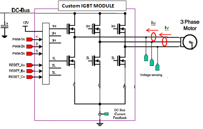
What are the InstaSPIN-FOC requirements on the current feedback sensors in case of the hall effect type?

I've read a lot about the ideal sampling windows for current sensing with shunt resistors, 2 or 3 shunts, op-amp slew rate for each case.. Could you please post some recommendations for the hall-effect sensors?

I already saw LEM manufacturer mentioned somewhere here, but I couldn't find any info on the actual bandwidth needed for the correct current sensing. Should the bandwidth match the PWM frequency? Is op-amp like AD8226 with a slew rate around 0.4 V/us fast enough? Since those sensors does not have an infinite bandwidth, would you recommend a filter to remove high frequency (noisy environment, long cables..)?

Thank you.

  • Hall effect current sensors allow you to continuously monitor the current of each phase, so you no longer care about finding an ideal window in a low side shunt, and taking a measurement exactly in the middle where an average current reading could presumably be obtained (though certainly isn't in non-linear switching environments with low inductance motors).

    You do still need to obtain an average current at a specific time (if you use MotorWare projects as is you will take the sample at t=0 of each timer PWM cycle)

    The hall sensors are typically giving out a continuous bi-polar voltage signal as a representation of the current being measured. You will still need to scale this to 0 to 3.3V (center your zero around a 1.65V refernence) to get to the ADC input pins, and make sure you follow the OffsetRecal feature of the software projects.

  • Hello Chris,

    thanks for your response. I cannot seem to figure out what I’m doing wrong with the InstaSPIN. We have developed an interface between proven IGBT high power stage and your ControlCard F28069MISO. It is based on TI hvkit. Three voltages are sampled, with a divider to 30V for 3.3V input and pole of 663Hz (just to be safe, we thought that our motor might require high PWM frequencies).

    As a current sense, we use two +-200A LEM current sensors on phases U and V, scaled to be centered around 1.65V, max voltage 3.3V. Polarity shown by red arrows, no inverting amp before sampling. To do the initial (safe) testing, LEM sensors have 10 turns on them, so the user.h is set to 52.8A (calculated to be a current range from 0 to 3.3V). Final design counts with much higher voltages and currents, but for development, everything (including used motor) is scaled down.  

    All used projects are for hvkit, with modified files for our hardware. Using Lab1 and debugger, I can confirm reading all three stable voltages in expected magnitude. The same goes for two current sensors, they are mapped correctly (shortening U motor wire to the ground gives 0V on U voltage and expected current on Iu. The same goes for Uv/Iv pair. DC bus compensation turned off as suggested in one of the previous posts (in ISR before calling the controller).

    Sampling sequence/pins modified in  void DRV_setupAdcs(DRV_Handle handle): 

    Ia - A3

    Ib - B1

    Va - B4

    Vb - B6

    Vc - B7

    PWM’s the same way as in the Hvkit (GPIO 0,1,2 for U,V,W), we use only one set of outputs, as the IGBT board deals with the switching and deadzone externally.

    In DRV_readAdcData, currents and voltages are mapped to the pAdcData variable, current Ic=0.

    During the identification procedure on following lab excercises (most of the time using proj_lab5b), it finds (stable) voltages and currents offsets. During Rs identification, I can see that Rs changes wildly all the time, ranging from ~0.005ohm to ~500ohm. On the osciloscope, I don’t see a reason for this behavior on the voltage/current inputs. After this, motor tries to spin with a rampup, producing some forced three phase waveform (clearly observable almost sinusoidal signal on the current sensors, voltages looks reasonable too). Then I’m suspecting comes the switch over to the FOC, which fails, motor stops spinning, wild voltage and current graphs, motor cogging, sometimes high current is observed from the suppy.

    I tried to change  bias += OFFSET_getOffset(obj->offsetHandle_I[cnt]);

    to both polarities (+ and -), which is supposed to be the only place necessary to the change for positive/negative current feedback. It didn't seem to affect the Rs identification. Yes, in user.h I’m defining that there are two current sensors. Always running in "do not use user.h, do Rs/offsets recalibration" mode

    Could you please suggest which way to proceed with finding the source of this problem? Since Rs identification is not correct, I suspect that it will be a very low level problem that must be solved before proceeding further in the identification process.

    Thanks!

  • There is a known bug in the User's Guide regarding current polarity. Please refer to this post:

    http://e2e.ti.com/support/microcontrollers/c2000/f/902/p/304553/1071283.aspx#1071283

    Basically, for positive current feedback you need

       In DRV_readAdcData in drv.h:

       pAdcData->I.value[0] = -value;

       and

       in DRV_updateAdcBias function in drv.h:

       bias -= OFFSET_getOffset(obj->offsetHandle_I[cnt]);

    For negative current feedback you need

       In DRV_readAdcData in drv.h:

       pAdcData->I.value[0] = value;

       and

       in DRV_updateAdcBias function in drv.h:

       bias += OFFSET_getOffset(obj->offsetHandle_I[cnt]);

    Now, an easy way to check this out is during Rs identification, measure current A on the scope. If the current amplitude matches what you have in USER_MOTOR_RES_EST_CURRENT, then your current feedback is fine.

    Seems to me that there is something to look for in the voltage feedback. Do you measure with the scope good signals from your voltage feedback? Please share with us your DRV_setupAdcs function, and if possible, more details on the hardware you have.

    As a sanity check, in CCS Register view window, check the ADC results register corresponding to the voltage feedback and see if they make sense.

    Also, I would suggest enabling DCbus compensation. This is to make sure the current controllers are scaled depending on DCbus.

    -Jorge

  • Great, that was actually very useful for me - I had no idea about this bug! Now I can confirm that my current value during Rs identification is stable and correct (observing input into ADC current). Voltage is stable as well (also looking with oscilloscope on the ADC input). But Rs is still being identified completely wrong. It is actually decreasing during the Rs identification - I extended the time in user.c to very long time constants, and I can see that in 20 seconds the Rs value constantly decreases to around 2.8E-7 Ohm.

    What was another problem is the fact that our IGBT module have only three inputs - one for each phase, and a global disable (opens all IGBTs, high Z). I added this global disable on/off into DRV_enablePwm and DRV_disablePwm functions. Is that enough? Or does InstaSPIN require having high Z on just one set of transistors in some moment? We cannot control them separately like that.

    Part of DRV_setupAdcs:

      // configure the interrupt sources
      ADC_disableInt(obj->adcHandle,ADC_IntNumber_1);
      ADC_setIntMode(obj->adcHandle,ADC_IntNumber_1,ADC_IntMode_ClearFlag);
      ADC_setIntSrc(obj->adcHandle,ADC_IntNumber_1,ADC_IntSrc_EOC7);

      ADC_setSocChanNumber(obj->adcHandle,ADC_SocNumber_0,ADC_SocChanNumber_A3);
      ADC_setSocTrigSrc(obj->adcHandle,ADC_SocNumber_0,ADC_SocTrigSrc_EPWM1_ADCSOCA);
      ADC_setSocSampleDelay(obj->adcHandle,ADC_SocNumber_0,ADC_SocSampleDelay_9_cycles);

      ADC_setSocChanNumber(obj->adcHandle,ADC_SocNumber_1,ADC_SocChanNumber_A3);    // Ia
      ADC_setSocTrigSrc(obj->adcHandle,ADC_SocNumber_1,ADC_SocTrigSrc_EPWM1_ADCSOCA);
      ADC_setSocSampleDelay(obj->adcHandle,ADC_SocNumber_1,ADC_SocSampleDelay_9_cycles);

      ADC_setSocChanNumber(obj->adcHandle,ADC_SocNumber_2,ADC_SocChanNumber_B1);    // Ib
      ADC_setSocTrigSrc(obj->adcHandle,ADC_SocNumber_2,ADC_SocTrigSrc_EPWM1_ADCSOCA);
      ADC_setSocSampleDelay(obj->adcHandle,ADC_SocNumber_2,ADC_SocSampleDelay_9_cycles);

      ADC_setSocChanNumber(obj->adcHandle,ADC_SocNumber_3,ADC_SocChanNumber_B4);    // Va
      ADC_setSocTrigSrc(obj->adcHandle,ADC_SocNumber_3,ADC_SocTrigSrc_EPWM1_ADCSOCA);
      ADC_setSocSampleDelay(obj->adcHandle,ADC_SocNumber_3,ADC_SocSampleDelay_9_cycles);

      ADC_setSocChanNumber(obj->adcHandle,ADC_SocNumber_4,ADC_SocChanNumber_B6);    // Vb
      ADC_setSocTrigSrc(obj->adcHandle,ADC_SocNumber_4,ADC_SocTrigSrc_EPWM1_ADCSOCA);
      ADC_setSocSampleDelay(obj->adcHandle,ADC_SocNumber_4,ADC_SocSampleDelay_9_cycles);

      ADC_setSocChanNumber(obj->adcHandle,ADC_SocNumber_5,ADC_SocChanNumber_B7);    // Vc
      ADC_setSocTrigSrc(obj->adcHandle,ADC_SocNumber_5,ADC_SocTrigSrc_EPWM1_ADCSOCA);
      ADC_setSocSampleDelay(obj->adcHandle,ADC_SocNumber_5,ADC_SocSampleDelay_9_cycles);

      ADC_setSocChanNumber(obj->adcHandle,ADC_SocNumber_6,ADC_SocChanNumber_A7);    // Vbus
      ADC_setSocTrigSrc(obj->adcHandle,ADC_SocNumber_6,ADC_SocTrigSrc_EPWM1_ADCSOCA);
      ADC_setSocSampleDelay(obj->adcHandle,ADC_SocNumber_6,ADC_SocSampleDelay_9_cycles);

      ADC_setSocChanNumber(obj->adcHandle,ADC_SocNumber_7,ADC_SocChanNumber_A7);    // Vbus
      ADC_setSocTrigSrc(obj->adcHandle,ADC_SocNumber_7,ADC_SocTrigSrc_EPWM1_ADCSOCA);
      ADC_setSocSampleDelay(obj->adcHandle,ADC_SocNumber_7,ADC_SocSampleDelay_9_cycles);

    Part of DRV_readAdcData:

    // convert current A
      // sample the first sample twice due to errata sprz342f, ignore the first sample
      value = (_iq)ADC_readResult(obj->adcHandle,ADC_ResultNumber_1);
      value = _IQ12mpy(value,current_sf) - obj->adcBias.I.value[0];      // divide by 2^numAdcBits = 2^12
      pAdcData->I.value[0] = value;

      current_c = value;
      // convert current B
      value = (_iq)ADC_readResult(obj->adcHandle,ADC_ResultNumber_2);
      value = _IQ12mpy(value,current_sf) - obj->adcBias.I.value[1];      // divide by 2^numAdcBits = 2^12
      pAdcData->I.value[1] = value;

    // convert voltage A
      value = (_iq)ADC_readResult(obj->adcHandle,ADC_ResultNumber_3);
      value = _IQ12mpy(value,voltage_sf) - obj->adcBias.V.value[0];      // divide by 2^numAdcBits = 2^12
      pAdcData->V.value[0] = value;

      // convert voltage B
      value = (_iq)ADC_readResult(obj->adcHandle,ADC_ResultNumber_4);
      value = _IQ12mpy(value,voltage_sf) - obj->adcBias.V.value[1];      // divide by 2^numAdcBits = 2^12
      pAdcData->V.value[1] = value;

      // convert voltage C
      value = (_iq)ADC_readResult(obj->adcHandle,ADC_ResultNumber_5);
      value = _IQ12mpy(value,voltage_sf) - obj->adcBias.V.value[2];      // divide by 2^numAdcBits = 2^12
      pAdcData->V.value[2] = value;

      // read the dcBus voltage value
      value = (_iq)ADC_readResult(obj->adcHandle,ADC_ResultNumber_6);     // divide by 2^numAdcBits = 2^12
      value = _IQ12mpy(value,voltage_sf);
      pAdcData->dcBus = value;

  • Let's look at the bias. Please add this to your watch window:

    drv.adcBias

    and when Rs is being identify, halt execution and send me the values you get on drv.adcBias (the entire structure of seven IQ24 values.

    Also, maybe you already checked this, but please confirm that you updated the filter pole (663 Hz?) to this define:

    #define USER_VOLTAGE_FILTER_POLE_Hz  (663.0)

    Thanks,

    -Jorge

  • Thanks,


    So I made two pictures, on the left with a power supply on, one on the right with a power supply off. It is clearly visible that there is quite a difference between them. I confirm the pole location in user.h

    Piece of relevant user.h:

    #define USER_IQ_FULL_SCALE_FREQ_Hz        (600.0)

    #define USER_IQ_FULL_SCALE_VOLTAGE_V      (30.189*3)

    #define USER_ADC_FULL_SCALE_VOLTAGE_V       (30.189)

    #define USER_IQ_FULL_SCALE_CURRENT_A          (20)

    #define USER_ADC_FULL_SCALE_CURRENT_A        (52.8)

    #define USER_NUM_CURRENT_SENSORS            (2)

    #define USER_NUM_VOLTAGE_SENSORS            (3)

  • I actually tried to read the values of voltages and currents during the ID procedure, and after the bias values are stored, I get negative voltages displayed during the rest of the ID process (currents are okay). To see what actual values of voltages and currents I'm getting, I wrote following the code into the mainISR

    // convert the ADC data
      DRV_readAdcData(drvHandle,&gAdcData);

      voltages[0] = _IQmpy(gAdcData.V.value[0],_IQ(USER_IQ_FULL_SCALE_VOLTAGE_V));
      voltages[1] = _IQmpy(gAdcData.V.value[1],_IQ(USER_IQ_FULL_SCALE_VOLTAGE_V));
      voltages[2] = _IQmpy(gAdcData.V.value[2],_IQ(USER_IQ_FULL_SCALE_VOLTAGE_V));

      currents[0] = _IQmpy(gAdcData.I.value[0],_IQ(USER_IQ_FULL_SCALE_CURRENT_A));
      currents[1] = _IQmpy(gAdcData.I.value[1],_IQ(USER_IQ_FULL_SCALE_CURRENT_A));
      currents[2] = _IQmpy(gAdcData.I.value[2],_IQ(USER_IQ_FULL_SCALE_CURRENT_A));

  • Michal,

    This is separate from the issue you are currently looking at, but I noticed your user.h settings and wanted to comment.


    #define USER_IQ_FULL_SCALE_FREQ_Hz        (600.0)

    #define USER_IQ_FULL_SCALE_VOLTAGE_V      (30.189*3)

    Why have you selected this value?  You should make this the minimum value that is greater than USER_MOTOR_FLUX_VpHz * USER_IQ_FULL_SCALE_FREQ_Hz  [assuming this is the maximum speed you expect to command].  with 30.189*3 V / 600 Hz, you are supporting a motor with flux of 0.15 V/Hz.

    Essentially, if this is a small flux machine, you want to reduce the IQ_VOLTAGE to get best resolution possible.  If it is a higher flux machine you want to increase IQ_VOLTAGE to larger than largest flux value to insure that all flux calculations remain bounded between a per unit -1.0 and 1.0

    #define USER_IQ_FULL_SCALE_CURRENT_A          (20)

    The IQ_CURRENT should always be >= ADC_CURRENT / 2.  Since ADC_CURRENT is bipolar, your 52.8A is a measurement of +/- 26.4A.  There is no reason to scale this to +/-20 as you will have peak values that fall outside of the -1.0 to 1.0 per unit range.  Set IQ_CURRENT to at least (26.4), or I usually just go up to another whole number value, like (28) or (30).

    #define USER_ADC_FULL_SCALE_CURRENT_A        (52.8)

  • Thanks Chris,


    Yes indeed that is wrong. Originally I had those set to different values, as I expected that it will be a short time before I see the ID successfully completed. I'm now waiting for the delivery of LaunchPad + motor driver board, because there are too many unknown variables in the system. I couldn't find much info about how the Rs ID actually works (what should be observed on the U,V,W phases), which direction the current is flowing in each phase, what to do if the Rs is in order of 10E6 or 10E-6, why there should be a different sign in the offset value (system is always centered around half of the ADC voltage, regardless the polarity), if there is any moment when both transistors in the bridge are off (not counting the dead zone), if this state is used for anything..

    I guess that this will be answered by having the actual working kit. I would like to add a couple of suggestions for the documentation and the code itself. But fist I have to get it operational, and I'm running out of time.

    Thanks for your support.

  • Doing a few calculations, based on section 6.5.2 of SPRUHJ1C, I calculate a Vbus of:

    Voltage_bias = 0.176

    USER_ADC_FULL_SCALE_VOLTAGE_V = 30.189

    USER_IQ_FULL_SCALE_VOLTAGE_V = 90.567

    USER_VOLTAGE_SF = USER_ADC_FULL_SCALE_VOLTAGE_V/USER_IQ_FULL_SCALE_VOLTAGE_V = 0.333

    Vbus = 2 * Voltage_bias * USER_ADC_FULL_SCALE_VOLTAGE_V / USER_VOLTAGE_SF

    Vbus = 31.8796

    This Vbus is higher than the measurable range by the ADC, which is 30.189.

    Could you confirm you have a Vbus that's measurable by the ADC?

    Could you confirm that during the offsets measurements (CTRL_State_OffLine) you have 50% duty cycles going to the motor windings? This would confirm that the inverter is ON, and that the driver stage doesn't modity the duty cycles in any way

    Bottom line, you shouldn't measure all negative values in the voltages, but you should measure values around zero, AC values.

    -Jorge

  • Thank you, Jorge.

    I added the DC bus sensor - as I mentioned before, my system does not contain DC bus measurement. Well, now it does.

    Using your calculations, I confirm that voltage offsets corresponds to the Vbus. Now I'm using voltages 20-30V , and all offsets scale accordingly. I had no idea it is centered like that! Being named as offsets, I suspected them to be an ADC offset with transistors grounded. That cost me quite some time, trying to figure out why my system is not measuring near-zero offset values. Now when you say that those are offsets related to the Vbus, it makes sense.


    I fixed my user.h file to be more close to the reality (IQ scaling)

    Yes, inverter has 50% duty cycle during offset calc.

    Now my problem is definitely in the current sensing. I would like to ask you for a definite guide to the current polarity and offsets. Just say which direction should be sensor mounted to keep the default (inverting) behavior, meaning:

    bias += OFFSET_getOffset(obj->offsetHandle_I[cnt]);

    ....

      pAdcData->I.value[0] = value;


    PS: Could there ever be a situation in which bias sign is "-" and value sign "+" ?

    While randomly changing the current feedback polarity, I either get Rs in very small numbers (>0.0001Ohm even with motor disconected), or very high currents and Rs in kOhms. My current sensors are working well, tested by other instruments.

  • Okay, I think I'm onto something. Those U,V,W phase voltages (sampled and with an offset) are indeed negative during the Rs calculation, and that causes Rs being close to 0 Ohm. The problem is, that the calibration will be done over 50% duty cycle with no current, making offset ~ 14.9V on each phase. But when the current starts flowing, voltage drops somewhere (I'm using a 40kW IGBT module). This drop would probably be too small to be noticed on ~500V DC supply, but since I'm using 30V supply, this drop creates approx. -0.5V on the phase voltage (with offset subtracted already). This would result in Rs=(-0.5V / 2A), which is of course nonsense.

    Now, how to compensate for such a drop? Obviously even when using an identified motor, the system will think it is spinning opposite direction, because thanks to the voltage drop, the phase voltage always seems to be negative.

    I tried to test this by taking one (similar) hobby motor with parameters from your user.h, and run it as mine motor. The loop was unstable, and when spinning, the system always estimated that the direction is opposite from desired.

  • Yes this is interesting, so please confirm, are you using high voltage high current IGBTs to control a low voltage motor? This might be an issue, just like you are seeing in your tests, the voltage drop in the high voltage IGBT and the switching speed of the IGBT might not be the best hardware for a low voltage motor.

    Is it possible for you to test our standard 8301 board to test your motor first?

    Not sure how to compensate for this if this is the issue. It makes sense though, that if you measure voltage offsets without current, and then while conducting current the IGBT has a big voltage drop, that will shift your offsets, but most importantly, the offsets will be changing from phase to phase, depending on current flowing through each IGBT.

    So what I suggest is for you to try our DRV8301 board to confirm this is the issue, and secondly, if you can select a power stage that matches your motor. If your switching frequency is high (especially if you have a low inductance motor) you might be better off with MOSFETs instead of IGBTs.

    -Jorge

  • Thanks Jorge,

    Indeed, I'm using 50kW IGBTs, in the final application there can be 200V to 500V (there are more modes of operation - when you get to certain speed region, it is better to raise the voltage), currents up to 200A.


    I ordered the BOOSTXL-DRV8301 before the New Year, it should be delivered every day now. My application will be using 90kg 20kW continuous induction motor, but as you can imagine, there is not much margin left for errors in that power range. Having one phase in a constant short means a lot of things and non of them are good.

    I really wanted to develop a complete, safe HW solution and then just rescale everything up by a factor of 10 by changing division factor/ number of turns on hall sensors, but now I see it is not possible.

    My idea now is to simply measure IGBT drop by shortening one phase to the ground through a known resistor, changing the current and measuring the phase voltage. Can you confirm that creating a lookup compensation table for this IGBT could solve this problem? After every ADC sample is taken during operation, depending on the current through this phase, the phase voltage is adjusted by a value in the table.

    Do you have any IGBT hardware for InstaSPIN? This should be observable on any IGBT system. Just in a smaller scale (1V error with a 200V bus compared to 1V on a 30V bus).

    I would like to discuss this in more detail, but I guess that a forum is not an ideal place for that.

  • Having a look up table (voltage drop versus current) to compensate for the voltage drop could help, the second issue I see is the dead time. Typically a low voltage MOSFET requires nearly no deadtime. For instance, our DRV8301 has a deadtime of 100 ns or so, so in a 10kHz to 20kHz PWM, this deadtime can be ignored.

    Yes, we have our high voltage kit (http://www.ti.com/tool/tmdshvmtrinspin), which uses an IGBT power module, but this is a high voltage kit, so a voltage drop of 1 V or so doesn't affect this reading as much as having a 30V Vbus.

    -Jorge

  • Deadtime is sorted out in the IGBT module and I have no control of it - there is no way to turn both transistors on at the same time. There is only one pin to control each set of IGBTs and one global disable (high Z). Nominal design PWM frequency is 20kHz, but it works higher (with lower efficiency probably). I will try to move to higher voltages as soon as possible. Also with Hall effect sensors you don't care about sampling windows and such.

    Thanks for your support, I will try to get it up and running and share my experience.

    PS: InstaSPIN algoritm could automatically correct for this with a little sw extension and no additional cost, but it is of course a question if it is worth it - as you are saying, there are no problems with your 200V system.

  • By the way, here are a few diagrams that might help on the current polarity question:


  • Yes, very illustrative. Thank you! It would be a good addition to the "designing your own system" chapter in the documentation.

  • Hi Jorge,

    I'm working on a design with a positive feedback (as described in SPRUHJ1F §5.2.2.1).
    The SPRUHJ1F explain that function HAL_updateAdcBias located in
    hal.h file, shall be changed with:
    bias -= OFFSET_getOffset(obj->offsetHandle_I[cnt]);

    Is it still mandatory to apply as described in this topic the negative sign change to the 3 currents converted value ?
    pAdcData->I.value[0] = value;
    pAdcData->I.value[1] = value;
    pAdcData->I.value[2] = value;

    Thanks for your support,
    Paul
  • In simple terms, current leaving the inverter should be treated as a positive current. Converge your logic to get that.

    rgds,

    ramesh

  • Hi Ramesh,

    Thank you for your feedback, ChrisClearMan has also sent me an answer in this other post (with the same subject):

    https://e2e.ti.com/support/microcontrollers/c2000/f/902/t/492014

    Now my hardware prototype really work's well I succeed to test it up to 3.5kW on brushless motors and also on a HVAC compressor. Motor parameter identification was a bit tricky on the HVAC compressor.

    Best regards,

    Paul

  • starting in MW 15 we changed this so you didn't have to negate the value for positive feedback.