This thread has been locked.

If you have a related question, please click the "Ask a related question" button in the top right corner. The newly created question will be automatically linked to this question.

LauchPad Eval Kit

Other Parts Discussed in Thread: CONTROLSUITE, MOTORWARE, LAUNCHXL-F28027F, BOOSTXL-DRV8301, DRV8302, DRV8312, UNIFLASH, TMS320F28027, LM3S1968

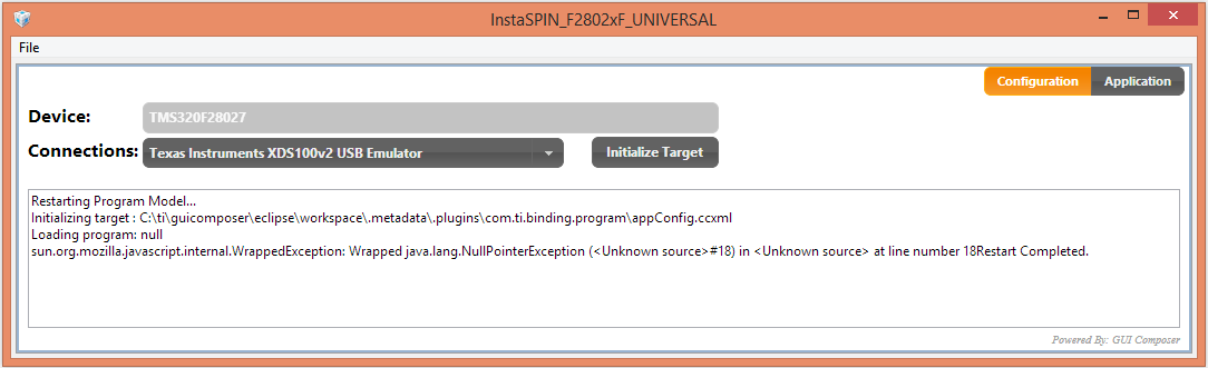
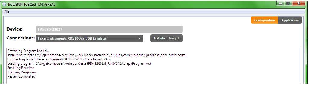
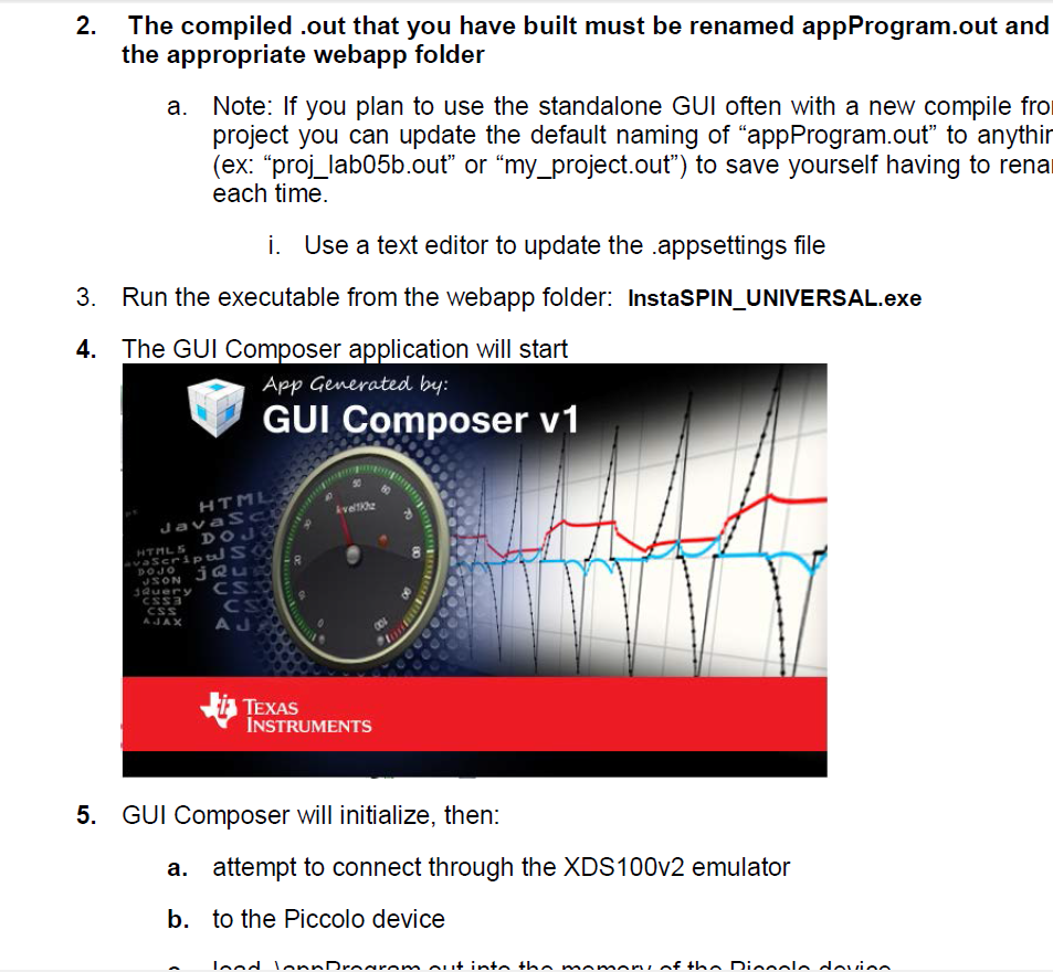
OK, so I have this kit and have lunched both controlsuite and motorware. BOTH! do not work as they state "C:ti/guicomposer/webapps/instaspin_f2802xf....." not found. There is in fact NO suck directory or file so of course it is going to fail!


I don't want to "develop" anything at the moment! I just want to spin a BLDC motor to do some engineering tests!


What in the world do I need to do to get this thing to run? The instructions are as useless as this Kit is at the moment, as it just instructs me to download instaspin (which I did) and the damn thing still does not want to launch or run anything.

Yes I am frustrated. You would be too after spending $800 on your kits that don't do a damn thing!

  • Hi Brad,

    If you are using LAUNCHXL-F28027F and BOOSTXL-DRV8301 please read and follow

    ti\motorware\motorware_1_01_00_12\docs\boards\kits\docs\readmefirst_instaspin_launchboost.pdf

    By the way, use 

    ti\motorware\motorware_1_01_00_12\MotorWare.exe

    To browse the resources and docs for your kits (sounds like you have multiple if you spent $800). 

  • Hello Chris,

    The only thing that happens when I do that is I get a "TI Resource Explorer" web page. When I go to the appropriate place Piccolo F2802xF\Launch Run Universal GUI. all I get is the error message previously provided.


    Same thing for instaspin! NIETHER work!

    Yes, I originally purchased the DRV8302 Kit, and found it did not work with my motor. So I ordered the DRV8312 thinking it would work better, but then during our conversation on the board you recommended the LuanchPad and Boostxl. Trying to return the DRV8312, but still spent almost $500 for stuff that to date has not worked.

    So what do you recommend now that I have already tried launching from the link you indicate but only get the message provided in the first email?

  • Brad,

    The solution to your problem is in the documentation. 

    The readmefirst document points you to the other guides and gives you the process to follow. 

    The GUI QSG is very clear about how to get the GUI working for this kit. 

  • Hello,

    Did you try to program this kit using CCS (any example is fine)? Did they work well?

    This kit is not plug and play to run the motor so you should program it first.

    If you want to use the GUI, it will download the program automatically but of course you need to INSTALL it first.

    I have this folder in my computer that you mentioned. I don't know how you missed this step.

    So like Chris said, you need to read the documentation.


    Good luck!

    Best regards,

    Maria

  • Hello Chris,

    With all due respect the issue is the lack of documentation that provides the needed information.

    Here is what I have, and what I followed!

    1) in the LaunchPad box is a single page instruction sheet. Number 1 instructs me to goto www.ti.com/c2000-launchpad-instaspin. When I go there, I have to search all over to even figure out what to download! So I get Instaspin and download it. When it downloads I click on the downloaded file "controlSUITE3.2.4setup" and it runs.

    2) after install I look at "getting started guide" and it states that I should see 3 dialog boxes! I see NONE during install! I have just re-installed the software to verify whether or not these dialogs show up, and they do not.

    So....... What documentation are you referring too? I am going by what I download and I receive in the KIT. This is the only documentation I have from what I have been provided with. I should not have to search the web to find documentation to make your boards work, as they should come with the product or in the download of the software.

    If I look in the Directory there IS NO READ ME FILE.

  • Brad,

    Ok, I''m putting myself in your shoes and I can see where you got a bit stumbled up.

    From www.ti.com/c2000-launchpad-instaspin it is never clear to download MotorWare.  This page has been completely redesigned since we launched the kit and is not clear enough I agree.  I will make sure thie gets improved. Thank you for informing me.

    If you somehow make it to the tool folder of the kit:
    www.ti.com/tool/launcxl-f28027f

    I believe it is more clear:

    If you install MotorWare, it will ask you if you want to launch, or you can launch directly from the latest revision:

    C:\ti\motorware\motorware_1_01_00_12\MotorWare.exe

    Here you can see all of your resources:

  • Hello Chris,

    Thanks for the reply.

    After having struggled for days, I do have things installed. However, now I can't find a flash program that will program the board. There is no recommendation in the documentation as to which flash tool to use, so from the ones I have downloaded so far I can't find the part name in the selection list that I need to flash.

    The only thing the documentation says is to "load" the out file.

    "Build lab5a, connect to the target and load the .out file." So how do you "load" the out file? What tool? In the Keil software this can be easily loaded right from the debugger. However, in CCS there does not appear to be any way to do this.

  • instaspin_labs.pdf

    In MotorWare. Step by step with pictures

    Sorry for brevity, plane doors are closing....

  • Hello Chris,


    Have a safe trip.

    Well when I build the program Lab5a, I get the following:

    C28xx: Loader: One or more sections of your program falls into a memory region that is not writable.  These regions will not actually be written to the target.  Check your linker configuration and/or memory map.

    When I try to debug, the evm never programs. I have gone into properties of the project and tried to change the device type, but even doing that the board never programs. And when I select .. Piccolo F28027 there is an error about not enough memory for the program.

    So this thing does not program per the instructions, which I have followed to the tee. I even started back on Lab1 and followed the directions starting from there, but the same thing. There appears to be a step, or two, that is missing in the instructions.

  • I have landed safely.

    Are you sure you have a LAUNCHXL-F28027F? 

    Note the F. The F version also has an InstaSPIN -FOC logo on the PCB. 

    And you are building the project from the boostxl-drv8301 board directory?

  • Hello Chris,


    Yep! Here is the path I am using.

    C:\ti\motorware\motorware_1_01_00_12\sw\solutions\instaspin_foc\boards\boostxldrv8301_revB\f28x\f2802xF\projects\ccs5\proj_lab05a


    I can simply "compile" the program fine. The issue is that I MUST use CCS Uniflash in order to even try to flash the device. So this is probably where the issue is coming from. Just doing a "run" does not load the device with the compiled code.

    So as stated before, there does appear to be a step or two missing in the documentation for what the user needs to do.

    So what step am I missing with this?

  • Hi Brad,

    1. Please confirm that your LaunchPad has the InstaSPIN FOC logo on the PCB

    2. Please confirm that you have removed the three jumpers JP1, JP2, JP3

    3. Please confirm that BoosterPack is installed in correct orientation (A,B,C phase connections on same side as USB connection) and you are providing 6-24V at PVDD and GND?

    4. Please confirm you have created a valid Target Configuration File as in this picture, or are pointing to the one provided in MotorWare: C:\ti\motorware\motorware_1_01_00_12\sw\ide\ccs\ccs5\targetConfigs\TMS320F28027_xds100v2.ccxml

    5. While in the CCS Edit Perspective, right click this target confit and Launch the configuration

    6. You will now be in the CCS Debug Perspective.  Click on Run --> Connect Target

    7. Select Run --> Load --> Load Program and select your .out  (mine is grey'd out because I do not have HW connected right now)

    8. This will flash the LaunchPad with your binary

    9. You can then click Run --> Resume and enable Real-time

    10. Instrument the project using View --> Expressions (you can load this expressions view by using View --> Scripting Console and selecting the matching proj_lab05a.js file) or by importing the Universal GUI by View --> GUI Composer --> Import, and pointing to a .zip of C:\ti\guicomposer\webapps\InstaSPIN_F2802xF_UNIVERSAL

    At which step do you have trouble?

    Also, I see you are starting with 5a.  That is fine, but please realize that you may need to use 2c to get proper motor parameters if your motor is low flux / low inductance / high speed.  Also note that lab3 educates you on the voltage and current offsets and the process of getting a user.h set for your specific motor and inverter hardware. There are settings in user.h used in 5a that you should be aware of.


  • Hello Chris,

    Thanks for this information.

    The first 4 items are confirmed.


    I do not have the "Launch Selected Configuration" in my menu though! (See screen shot)

    Nor do I have the other items that you show in your post. This is the first time I am working with CCS, as I usually use Keil so this is a completely different way to run things than Kiel does things.

  • In your first image you are trying to Launch the Configuration from your Project.  Per my instruction you need to go to
    View --> Target Configurations

    and Launch from there:

    For your second image note that you ware in the "CCS" Edit Perspective because you have not launched a debug session.  Per my instruction click on "CCS Debug" to switch to the Debug Perspective where you can connect the debugger to the target and load your coade.

    The CCS Debug and CCS Edit buttons should be at the top of a tab, usually in the right hand corner. You can see them in my image in this post.


  • Hello Chris,


    Sorry for the late reply, have had other priorities to work on.


    The first issue was all on me, and sorry for that!

    However, even after launching the configuration when I go to the run there is no Connect enabled, and yes I am in the CCS Debug mode (see below).

    Luanch:

  • Hello Brad,

    Can you try these steps below:

    If it is success, it will enter the debug session and load the program:

    When it is finished loading the program, the debug session is ready to be used.

    Let us know your result.

    Best regards,

    Maria

  • Hello Maria,


    The program still will not build.

    "../28027_RAM_lnk.cmd", line 114: error #10099-D: program will not fit into

       available memory.  placement with alignment/blocking fails for section
    >> Compilation failure
       ".text" size 0x3330 page 0.  Available memory ranges:
       PRAML0       size: 0x900        unused: 0x823        max hole: 0x823     
    "../28027_RAM_lnk.cmd", line 113: error #10099-D: program will not fit into

    I have tried changing the "Variant" in the "Project" settings for several of the selections but still get the same error message.

    Does TI have a GUI based application that I can use to simply test a motor????? I have been at this way to long and have not gotten anything accomplished.

  • Brad,

    All of the projects in:

    C:\ti\motorware\motorware_1_01_00_12\sw\solutions\instaspin_foc\boards\boostxldrv8301_revB\f28x\f2802xF\projects\ccs5

    Come pre-set to build for FLASH operation.  How in the world did you manage to change configuration to build for RAM?

    Also, "28027_RAM_link.cmd" is not even used by any MotorWare project....

    So, what exactly have you done? What projects have you imported?

    It is SO simple.

    1. Import MotorWare projects for your combination of inverter + MCU.
    2. Update user.h has directed in the documentation.
    3. Build the project.
    4. Connect and load in CCS, or copy the .out to the \guicomposer\ folder, rename to appProgram.out, and launch the .exe

    Yes, we offer a GUI to instrument ANY MotorWare project.  But you first have to build a project specifically for your type of motor.  This is because our same software solution works for tiny little high speed motors up to huge high voltage motors.  You have to tell the software which type you are using.

    All of this is documented....we have thousands of people using this software on a daily basis. 


  • First, it was for the FACT that ZERO instructions came with this damn project that I had to try and figure out how to make this piece of cap project work.

    You even admitted that the Web site I was directed to from the single page with one Web link on it was changed and was not intuitive where to find the documents.

    Second, this is the first software tool that I have ever had this much problems with. I have used lm3s1968 project in Kiel in seconds after opening the evm. 

    You need to reexamine the shitty documentation you send out with your products. 

    "All of this is documented" WHERE???? Certainly not in ANY documentation I received in my kit. Why do I need to serf your Web page to determine how to make your shitty kit work? Provide the damn documents with the kits!!!!!

  • Brad,

    Everything is accessible through MotorWare.exe as I explained previously. 

    Message me and I will give you an address to return your kit. I will happily  refund out of my own pocket. 

    Thanks 

  • to offer one more olive branch, tell me everything you know about your motor and I will build an appProgram.out for you that you can place at

    C:\ti\guicomposer\webapps\InstaSPIN_F2802xF_UNIVERSAL\

    and then just run InstaSPIN_UNIVERSAL.exe

    Bus Voltage
    Max Current
    # of poles
    Maximum expected speed (RPM or Hz)


  • Thanks, but how is that going to help when by following the instructions nothing works?

    Here is my motor information anyway.....

    -------------------------------------------------------------------------------------------------------------------------------------


    1) I re-installed motorware to provide a new project file.

    2) recopiled project5a

    3) copied over the *.out file (renamed to appProgram.out) to "C:\ti\guicomposer\webapps\InstaSPIN_F2802xF_UNIVERSAL" then launched InstaSPIN_UNIVERSAL. All I get is the following.

    This is what the instructions say it should do.

    Nothing even close!

    This is why my frustration with this project is so high! Even when I remove, re-install, try from scratch (PER BATUM) follow the the instructions line for line the tools still do not do what the instructions say they should.

    Here is what is in my "default" .appsettings file.

    {"default": {
        "connection": "Texas Instruments XDS100v2 USB Emulator",
        "deviceFilter": "",
        "program": "appProgram.out",
        "device": "TMS320F28027",
        "connectionFilter": ""
    }}

    This is after another uninstall and install of the guicoposer.exe.

    Board is connected via USB, with 14V applied to the Boostxl board, and the motor connected.

  • Forgot the motor information in my rush to get to a birthday party.

    http://www.hobbypartz.com/07e-ezrun-sl-3656-4700kv-black-motor.html

  • Well, not connecting is a different issue.  There isn't a reason you shouldn't be able to connect.

    1. Jumpers removed from LAUNCHXL-F28027F

    2. LaunchPad Boot mode switches in correct settings: ON-ON-ON

    3. BoosterPack connected with proper orientation (all connectors on boosterpack should be on same side as USB of LaunchPad)

    4. 6-24V at BoosterPack PWR-GND pins

    5. USB connected to PC.  PC should "find hardware and install drivers". You can check under Windows Device Manger to make sure that it is finding Texas Instruments XDS100.


    Back to your motor.

    Web page says 4 poles (2 pairs).
    4700 KV = 14V * 4700 RPM/V =  65800 RPM; * 4 poles / 120 = 2193 Hz. 

    2193 Hz is NOT natively supported by this hardware configuration. There is a limit for our FULL_SCALE_FREQ of 4 * the HW voltage filter pole. On this inverter that filter pole is USER_VOLTAGE_FILTER_POLE_Hz (364.482).  This gives a maximum FULL_SCALE_FREQ of 1450 Hz.  However, with the InstaSPIN-FOC projects we can accept speed commands/estimates up to 2x the FULL_SCALE_FREQ, so we should be ok in regards to variable scale.  I set this to (1300.0) in the user.h I will attach. 

    2043.user.h

    Attached is the appProgram.out I built for you.

    http://e2e.ti.com/cfs-file.ashx/__key/communityserver-discussions-components-files/902/6354.appProgram.out

    screenshot of the GUI Composer .exe successfully launched

    and then the application


    This project will only help to ID the parameters.  You can NOT run the motor with this project.

    You will have to provide me back your ID'd Rs, Ls, and Flux values so you can update your user.h

    #elif (USER_MOTOR == EZRUN_3656)
    #define USER_MOTOR_TYPE                 MOTOR_Type_Pm
    #define USER_MOTOR_NUM_POLE_PAIRS       (2)
    #define USER_MOTOR_Rr                   (NULL)
    #define USER_MOTOR_Rs                   (0.034)  // guess
    #define USER_MOTOR_Ls_d                 (0.000005)  // guess
    #define USER_MOTOR_Ls_q                 (0.00005)  // guess
    #define USER_MOTOR_RATED_FLUX           (0.002)  // guess
    #define USER_MOTOR_MAGNETIZING_CURRENT  (NULL)
    #define USER_MOTOR_RES_EST_CURRENT      (1.5)
    #define USER_MOTOR_IND_EST_CURRENT      (-1.0)
    #define USER_MOTOR_MAX_CURRENT          (10.0)
    #define USER_MOTOR_FLUX_EST_FREQ_Hz     (100.0)


    If we get good values you can then run proj_lab05a in torque mode to see how the core sensorless FOC torque mode performs.


  • OK, progress......


    I was able to launch using your file and ran your out file.

    Here are the values it gave.

    RS = 0.0043

    LS = 0.3242

    Flux = 0.0049

  • Well, the Ls value certainly isn't valid. This give an Rs / Ls (H, the display is mH) = 13.27 Hz.  You should be expecting something > 2 kHz, and likely much higher. That would require about 2uH. 

    I've very surprised the Rs is so low.  I expected it to be a factor of 10 higher.

    Did the motor spin the entire time from EST_STATE_RampUp until it completed?


  • The motor did NOT spin at all. I could hear the PWMs pumping trying to work, and thought this was part of the program means to calculate the values you wanted.

  • Brad,

    I can't find a true spec on the motor that tells me the current, but I found another page that is selling a 120A continuous controller to go with it....so this motor may be out of the range of a 10A BoosterPack. However, unloaded (no prop) you should still be able to ID and then run.

    in attached I upped the RES_CURRENT to 3.0

    Please let me know if it starts spinning during the RampUp state of estimation. If it doesn't, try giving it a little spin with your fingers to overcome the cogging torque.

    If it does, please note if it spins for the next ~1.5 minutes til RampDown, or if it ends early note at which EST_STATE it stops.


    BTW - you've chosen about the hardest motor possible for a sensorless FOC technique. Congrratulations?


    appProgram.out
  • This time the motor made a bunch of noise, but would not turn even with me trying to spin it manually.

    Unfortunately it just works out that way. This is a motor that I need for the torque capability and the speed.

  • Brad,

    Give this a try, it's proj_lab5a (Torque mode, no speed controller) which I built with the following params:

    #define USER_MOTOR_Rs                   (0.0043)  // ID'd
    #define USER_MOTOR_Ls_d                 (0.000002)  // guess to hit Hz
    #define USER_MOTOR_Ls_q                 (0.000002)  // guess to hit Hz
    #define USER_MOTOR_RATED_FLUX           (0.0049)  // ID'd

    Make sure you have all the blue boxes checked, then click Run.

    The Resistance will recalibrate for about 8 seconds, then it will go into:

    You can now enter a Torque command, in Amps.

    Note that this Iq_ref_A does NOT have a limit.  If you put in 100 it will set 100 as the Iq_Ref input to the PI controller. If your motor had a load I'm sure it could take more than the 10A that the BOOSTXL can supply, and you would dame the board.


    See if your motor runs....


    If these are actually the params of your motor (2uH), this is going to be extremely challenging for a current control based motor control solution. If you MUST use this motor you will probably find it easier to use an ESC specially designed for this motor. They typically do current limiting (not control) through a comparator threshold and they vary the duty to the motor by varying the Vbus.  It is very different from what we in the industry (not just TI) do with Field Oriented Control.  Hobby motors are a different breed...they have been completely "mis-designed" (ridiculously low Ls) for these archaic control techniques.  The motor could be made cheaper and actually give better performance if they were designed like "normal" motors....which some of our customers are now doing.

    BTW - why do have to use an off the shelf hobby motor? There are plenty of other motors that can produce torque you require.  A hobby motor is about the worst motor you could choose to work with!


  • Regarding your motor question. 

    The issue is that no other Motor had the speed I need. This is for a new robotic cleaner, and it needs to have the vacuum motor spin 2x faster than an ac vacuum (30k). We have a 3x gearing to step up the fan speed to obtain the needed speed. But the motor needs the torque capability to ensure the fan spins fast enough and overcomes the friction involved. 

    No other motor, within reason, will do this. Trust me I have worked with multiple motor vendors who cannot meet this requirement. This motor is 2x better in speed and torque for any motor that is 3x it's size.

  • Is this just going to run at one speed?

    You may want to consider a true BLDC technique. FOC is better for start-up, variable speed/load, and buys you a bit on overall efficiency in most applications. But if you are just running full out, a BLDC technique may be easier to implement.  

    I'm trying to find this motor locally before I order from online. Want to prove that we CAN run it. 

  • Variable speed. If the robot approaches a rug, the vacuum will be slowed down. Or the user can use a slower speed if they use the accessories to vacuum something delicate, such as their pet.

  • This works, but my supply will only handle 5A, and so the motor won't run at full speed. I am in the process of looking for another power supply online that I can order to get me more current.

  • Brad,

    today I purchased a Tekin Pro 4600kV motor.

    @ 18V with 4 poles that is 82,800 RPM and 2760 Hz!!!

    The really scary thing is that the ESC they recommend for this can handle 210A!  Are you going to have a 200A inverter in a vacuum cleaner? 

    I wanted to give this a try myself....and I suspect I will run into multiple issues as you did.

    • Max Hz well beyond the kit capability (~1400 Hz, can about double that if necessary but voltage filtering gets bad)
    • Major, major current draw (even unloaded) and I"m expecting some really nasty spikes on start-up and commutation

    I'm going to start playing with it tomorrow if I have time, will keep you updated.


  • It actually ID'd quite easily. These inboard motors are much easier than the outboard motors.

    #elif (USER_MOTOR == TEKIN_PRO4_4600KV)
    #define USER_MOTOR_TYPE                 MOTOR_Type_Pm
    #define USER_MOTOR_NUM_POLE_PAIRS       (2)
    #define USER_MOTOR_Rr                   (NULL)
    #define USER_MOTOR_Rs                   (0.0177)  // ID'd
    #define USER_MOTOR_Ls_d                 (0.0000014)  // ID'd
    #define USER_MOTOR_Ls_q                 (0.0000014)  // ID'd
    #define USER_MOTOR_RATED_FLUX           (0.00415)  // ID'd
    #define USER_MOTOR_MAGNETIZING_CURRENT  (NULL)
    #define USER_MOTOR_RES_EST_CURRENT      (5.0)
    #define USER_MOTOR_IND_EST_CURRENT      (-4.0)
    #define USER_MOTOR_MAX_CURRENT          (10.0)
    #define USER_MOTOR_FLUX_EST_FREQ_Hz     (150.0)


    The problem I'm going to run into is with the top frequencies.  I will need my CURRENT controller and EST frequency to be high enough (from a controls theory standpoint)....but this uses more MIPS and I don't have enough in this 60 MHz F28027F.  This is why ultra high speed motor controls use our 150 MHz+ Deflino products....simply control theory.


    here it is running with 0.5A of Iq torque command  (took 2.0 to start-up) at 44 KRPM.  The currents are bouncing around though...I'm only using 45 KHz PWM and this motor has only 1.4uH of inductance! 

  • I tried 80 kHz PWM and it's still really noisy.

    I'm not feeling so confident that a current controlled FOC approach is going to work for a motor like this.  External inductors are likely going to be required.