This thread has been locked.

If you have a related question, please click the "Ask a related question" button in the top right corner. The newly created question will be automatically linked to this question.

Unstable operation in the overmodulation range

Other Parts Discussed in Thread: MOTORWARE


With PMSM motors that have an Inductance value > 30mH the motor current gets unstable in the overmodulation range

I have been able to stabilize the current by reducing the current loop gain KpIdq and/or reducing the inductance value in the User.h file by 10 -15%

The Max voltage is set to .5774. The current is stable if max voltage is limited to 0.5

If the motor inductance is less than 30mH the current is stable through the full over modulation range

I am using a custom board with the software based on Project10a but I have also tested the motor with the High voltage kit evaluation board and Project 10a and the current also gets unstable  .


Motorware 15

Started with Project 10a

Custom board

  • it's interesting you are seeing this with higher Ls. Typically lower Ls values will have more current ripple and current noise, making overmodulation more challenging.

    are you sure this isn't a speed control issue? speed controllers may need to be adjusted less stiff at higher modulation (and into field weakening). One way to test this would be to implement the Torque control mode of lab05a into lab10a.

    lowering the Ls as you did usually has a positive effect on the FAST observer if you are seeing feedback instability. Especially under high load the Ls value can actually decrease, so lowering it after observing this behavior during testing is sound.


    have you tried adjusting the MinWidth or CmpOffset?
  • Hi Chris,

    I tried the following changes but adjusting the Ls and the current controller is the only things that made a different so far.

    1. Speed controller: I decreased the gains but it did not make a difference

    2. CmpOffset: (gCmpOffset = (int16_t) (1.0 * USER_SYSTEM_FREQ_MHZ);) I changed the default value of 1us to 3 us and it did not have an effect good or bad.

    4. Changed the external opamps

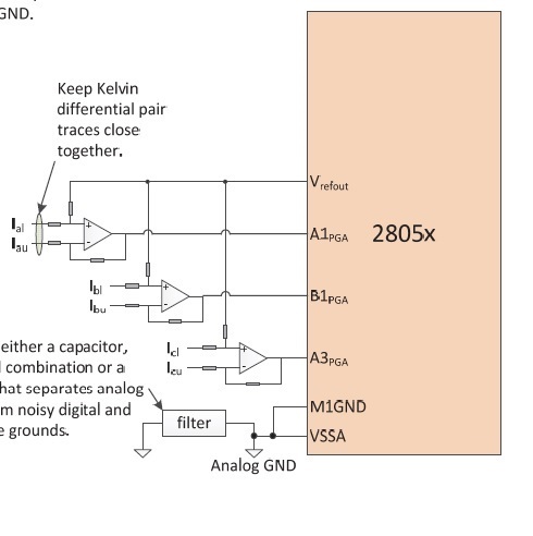
    I am using the 28052F with the internal opamps for the current feedback. Is there any limitations with the internal opamps?

    I am using the configuration shown in Spry234.pdf

    The external opamps have a slew rate of 1V/us, I have also tested with an opamp that has a slew rate of 10V/us and it did not make a difference.

    I will test the torque mode and the MinWidth tomorrow. The MinWidth sets the minimum pulse width for the PWM. Correct? float_t minWidth_microseconds = 2.0;

    How can I change the Ls value while the control is online? Right now I change it in the User.h file. I would like to adjust it based on frequency and load.

  • there are EST functions to set Ls _d and Ls_q
    extern void EST_setLs_d_pu(EST_Handle handle,const _iq Ls_d_pu);
    extern void EST_setLs_q_pu(EST_Handle handle,const _iq Ls_q_pu);

    I'll forward this to someone else to see if they have any ideas also
  • Hello Linley,

    It's not easy to find the root cuase with your limited information. Would you pls attache your User.h file?

    Regards,

    Steve Lim

  • Hi Steve,

    See the User.h file below. The motor parameters are under My_Motor_1


    #ifndef _USER_H_ #define _USER_H_ /* --COPYRIGHT--,BSD * Copyright (c) 2012, Texas Instruments Incorporated * All rights reserved. * * Redistribution and use in source and binary forms, with or without * modification, are permitted provided that the following conditions * are met: * * * Redistributions of source code must retain the above copyright * notice, this list of conditions and the following disclaimer. * * * Redistributions in binary form must reproduce the above copyright * notice, this list of conditions and the following disclaimer in the * documentation and/or other materials provided with the distribution. * * * Neither the name of Texas Instruments Incorporated nor the names of * its contributors may be used to endorse or promote products derived * from this software without specific prior written permission. * * THIS SOFTWARE IS PROVIDED BY THE COPYRIGHT HOLDERS AND CONTRIBUTORS "AS IS" * AND ANY EXPRESS OR IMPLIED WARRANTIES, INCLUDING, BUT NOT LIMITED TO, * THE IMPLIED WARRANTIES OF MERCHANTABILITY AND FITNESS FOR A PARTICULAR * PURPOSE ARE DISCLAIMED. IN NO EVENT SHALL THE COPYRIGHT OWNER OR * CONTRIBUTORS BE LIABLE FOR ANY DIRECT, INDIRECT, INCIDENTAL, SPECIAL, * EXEMPLARY, OR CONSEQUENTIAL DAMAGES (INCLUDING, BUT NOT LIMITED TO, * PROCUREMENT OF SUBSTITUTE GOODS OR SERVICES; LOSS OF USE, DATA, OR PROFITS; * OR BUSINESS INTERRUPTION) HOWEVER CAUSED AND ON ANY THEORY OF LIABILITY, * WHETHER IN CONTRACT, STRICT LIABILITY, OR TORT (INCLUDING NEGLIGENCE OR * OTHERWISE) ARISING IN ANY WAY OUT OF THE USE OF THIS SOFTWARE, * EVEN IF ADVISED OF THE POSSIBILITY OF SUCH DAMAGE. * --/COPYRIGHT--*/ //! \file solutions/instaspin_foc/boards/hvkit_rev1p1/f28x/f2805xF/src/user.h //! \brief Contains the public interface for user initialization data for the CTRL, HAL, and EST modules //! //! (C) Copyright 2012, Texas Instruments, Inc. // ************************************************************************** // the includes // modules #include "sw/modules/types/src/types.h" #include "sw/modules/motor/src/32b/motor.h" #include "sw/modules/est/src/32b/est.h" #include "sw/modules/est/src/est_states.h" #include "sw/modules/est/src/est_Flux_states.h" #include "sw/modules/est/src/est_Ls_states.h" #include "sw/modules/est/src/est_Rs_states.h" #include "sw/modules/ctrl/src/32b/ctrl_obj.h" // platforms #include "sw/modules/fast/src/32b/userParams.h" //! //! //! \defgroup USER USER //! //@{ #ifdef __cplusplus extern "C" { #endif // ************************************************************************** // the defines //! \brief CURRENTS AND VOLTAGES // ************************************************************************** //! \brief Defines the full scale frequency for IQ variable, Hz //! \brief All frequencies are converted into (pu) based on the ratio to this value //! \brief this value MUST be larger than the maximum speed that you are expecting from the motor #define USER_IQ_FULL_SCALE_FREQ_Hz (130.0) // 800 Example with buffer for 8-pole 6 KRPM motor to be run to 10 KRPM with field weakening; Hz =(RPM * Poles) / 120 //! \brief Defines full scale value for the IQ30 variable of Voltage inside the system //! \brief All voltages are converted into (pu) based on the ratio to this value //! \brief WARNING: this value MUST meet the following condition: USER_IQ_FULL_SCALE_VOLTAGE_V > 0.5 * USER_MOTOR_MAX_CURRENT * USER_MOTOR_Ls_d * USER_VOLTAGE_FILTER_POLE_rps, //! \brief WARNING: otherwise the value can saturate and roll-over, causing an inaccurate value //! \brief WARNING: this value is OFTEN greater than the maximum measured ADC value, especially with high Bemf motors operating at higher than rated speeds //! \brief WARNING: if you know the value of your Bemf constant, and you know you are operating at a multiple speed due to field weakening, be sure to set this value higher than the expected Bemf voltage //! \brief It is recommended to start with a value ~3x greater than the USER_ADC_FULL_SCALE_VOLTAGE_V and increase to 4-5x if scenarios where a Bemf calculation may exceed these limits //! \brief This value is also used to calculate the minimum flux value: USER_IQ_FULL_SCALE_VOLTAGE_V/USER_EST_FREQ_Hz/0.7 #define USER_IQ_FULL_SCALE_VOLTAGE_V (450.0) // 450.0 Example for hvkit_rev1p1 typical usage //! \brief Defines the maximum voltage at the input to the AD converter //! \brief The value that will be represented by the maximum ADC input (3.3V) and conversion (0FFFh) //! \brief Hardware dependent, this should be based on the voltage sensing and scaling to the ADC input #define USER_ADC_FULL_SCALE_VOLTAGE_V (409.6) // 409.6 hvkit_rev1p1 voltage scaling //! \brief Defines the voltage scale factor for the system //! \brief Compile time calculation for scale factor (ratio) used throughout the system #define USER_VOLTAGE_SF ((float_t)((USER_ADC_FULL_SCALE_VOLTAGE_V)/(USER_IQ_FULL_SCALE_VOLTAGE_V))) //! \brief Defines the full scale current for the IQ variables, A //! \brief All currents are converted into (pu) based on the ratio to this value //! \brief WARNING: this value MUST be larger than the maximum current readings that you are expecting from the motor or the reading will roll over to 0, creating a control issue #define USER_IQ_FULL_SCALE_CURRENT_A (10.0) // 10.0 Example for hvkit_rev1p1 typical usage //! \brief Defines the maximum current at the AD converter //! \brief The value that will be represented by the maximum ADC input (3.3V) and conversion (0FFFh) //! \brief Hardware dependent, this should be based on the current sensing and scaling to the ADC input #define USER_ADC_FULL_SCALE_CURRENT_A (19.04) //(19.89) // 19.89 hvkit_rev1p1 current scaling //! \brief Defines the current scale factor for the system //! \brief Compile time calculation for scale factor (ratio) used throughout the system #define USER_CURRENT_SF ((float_t)((USER_ADC_FULL_SCALE_CURRENT_A)/(USER_IQ_FULL_SCALE_CURRENT_A))) //! \brief Defines the number of current sensors used //! \brief Defined by the hardware capability present //! \brief May be (2) or (3) #define USER_NUM_CURRENT_SENSORS (3) // 3 Preferred setting for best performance across full speed range, allows for 100% duty cycle //! \brief Defines the number of voltage (phase) sensors //! \brief Must be (3) #define USER_NUM_VOLTAGE_SENSORS (3) // 3 Required //! \brief ADC current offsets for A, B, and C phases //! \brief One-time hardware dependent, though the calibration can be done at run-time as well //! \brief After initial board calibration these values should be updated for your specific hardware so they are available after compile in the binary to be loaded to the controller #define I_A_offset (0.8872208595) #define I_B_offset (0.9106488228) #define I_C_offset (0.8885936141) //! \brief ADC voltage offsets for A, B, and C phases //! \brief One-time hardware dependent, though the calibration can be done at run-time as well //! \brief After initial board calibration these values should be updated for your specific hardware so they are available after compile in the binary to be loaded to the controller #define V_A_offset (0.3765048981) #define V_B_offset (0.3758447766) #define V_C_offset (0.3739441037) //! \brief CLOCKS & TIMERS // ************************************************************************** //! \brief Defines the system clock frequency, MHz #define USER_SYSTEM_FREQ_MHz (60.0) //! \brief Defines the Pulse Width Modulation (PWM) frequency, kHz //! \brief PWM frequency can be set directly here up to 30 KHz safely (60 KHz MAX in some cases) //! \brief For higher PWM frequencies (60 KHz+ typical for low inductance, high current ripple motors) it is recommended to use the ePWM hardware //! \brief and adjustable ADC SOC to decimate the ADC conversion done interrupt to the control system, or to use the software Que example. //! \brief Otherwise you risk missing interrupts and disrupting the timing of the control state machine #define USER_PWM_FREQ_kHz (15.0) //30.0 Example, 8.0 - 30.0 KHz typical; 45-80 KHz may be required for very low inductance, high speed motors //! \brief Defines the maximum Voltage vector (Vs) magnitude allowed. This value sets the maximum magnitude for the output of the //! \brief Id and Iq PI current controllers. The Id and Iq current controller outputs are Vd and Vq. //! \brief The relationship between Vs, Vd, and Vq is: Vs = sqrt(Vd^2 + Vq^2). In this FOC controller, the //! \brief Vd value is set equal to USER_MAX_VS_MAG*USER_VD_MAG_FACTOR. Vq = sqrt(USER_MAX_VS_MAG^2 - Vd^2). //! \brief Set USER_MAX_VS_MAG = 0.5 for a pure sinewave with a peak at SQRT(3)/2 = 86.6% duty cycle. No current reconstruction is needed for this scenario. //! \brief Set USER_MAX_VS_MAG = 1/SQRT(3) = 0.5774 for a pure sinewave with a peak at 100% duty cycle. Current reconstruction will be needed for this scenario (Lab10a-x). //! \brief Set USER_MAX_VS_MAG = 2/3 = 0.6666 to create a trapezoidal voltage waveform. Current reconstruction will be needed for this scenario (Lab10a-x). //! \brief For space vector over-modulation, see lab 10 for details on system requirements that will allow the SVM generator to go all the way to trapezoidal. #define USER_MAX_VS_MAG_PU (2.0/3.0) // Set to 0.5 if a current reconstruction technique is not used. Look at the module svgen_current in lab10a-x for more info. //! \brief Defines the Pulse Width Modulation (PWM) period, usec //! \brief Compile time calculation #define USER_PWM_PERIOD_usec (1000.0/USER_PWM_FREQ_kHz) //! \brief Defines the Interrupt Service Routine (ISR) frequency, Hz //! #define USER_ISR_FREQ_Hz ((float_t)USER_PWM_FREQ_kHz * 1000.0 / (float_t)USER_NUM_PWM_TICKS_PER_ISR_TICK) //! \brief Defines the Interrupt Service Routine (ISR) period, usec //! #define USER_ISR_PERIOD_usec (USER_PWM_PERIOD_usec * (float_t)USER_NUM_PWM_TICKS_PER_ISR_TICK) //! \brief DECIMATION // ************************************************************************** //! \brief Defines the number of pwm clock ticks per isr clock tick //! Note: Valid values are 1, 2 or 3 only #define USER_NUM_PWM_TICKS_PER_ISR_TICK (2) //! \brief Defines the number of isr ticks (hardware) per controller clock tick (software) //! \brief Controller clock tick (CTRL) is the main clock used for all timing in the software //! \brief Typically the PWM Frequency triggers (can be decimated by the ePWM hardware for less overhead) an ADC SOC //! \brief ADC SOC triggers an ADC Conversion Done //! \brief ADC Conversion Done triggers ISR //! \brief This relates the hardware ISR rate to the software controller rate //! \brief Typcially want to consider some form of decimation (ePWM hardware, CURRENT or EST) over 16KHz ISR to insure interrupt completes and leaves time for background tasks #define USER_NUM_ISR_TICKS_PER_CTRL_TICK (1) // 2 Example, controller clock rate (CTRL) runs at PWM / 2; ex 30 KHz PWM, 15 KHz control //! \brief Defines the number of controller clock ticks per current controller clock tick //! \brief Relationship of controller clock rate to current controller (FOC) rate #define USER_NUM_CTRL_TICKS_PER_CURRENT_TICK (1) // 1 Typical, Forward FOC current controller (Iq/Id/IPARK/SVPWM) runs at same rate as CTRL. //! \brief Defines the number of controller clock ticks per estimator clock tick //! \brief Relationship of controller clock rate to estimator (FAST) rate //! \brief Depends on needed dynamic performance, FAST provides very good results as low as 1 KHz while more dynamic or high speed applications may require up to 15 KHz #define USER_NUM_CTRL_TICKS_PER_EST_TICK (1) // 1 Typical, FAST estimator runs at same rate as CTRL; //! \brief Defines the number of controller clock ticks per speed controller clock tick //! \brief Relationship of controller clock rate to speed loop rate #define USER_NUM_CTRL_TICKS_PER_SPEED_TICK (15) // 15 Typical to match PWM, ex: 15KHz PWM, controller, and current loop, 1KHz speed loop //! \brief Defines the number of controller clock ticks per trajectory clock tick //! \brief Relationship of controller clock rate to trajectory loop rate //! \brief Typically the same as the speed rate #define USER_NUM_CTRL_TICKS_PER_TRAJ_TICK (15) // 15 Typical to match PWM, ex: 10KHz controller & current loop, 1KHz speed loop, 1 KHz Trajectory //! \brief Defines the controller frequency, Hz //! \brief Compile time calculation #define USER_CTRL_FREQ_Hz (uint_least32_t)(USER_ISR_FREQ_Hz/USER_NUM_ISR_TICKS_PER_CTRL_TICK) //! \brief Defines the estimator frequency, Hz //! \brief Compile time calculation #define USER_EST_FREQ_Hz (uint_least32_t)(USER_CTRL_FREQ_Hz/USER_NUM_CTRL_TICKS_PER_EST_TICK) //! \brief Defines the trajectory frequency, Hz //! \brief Compile time calculation #define USER_TRAJ_FREQ_Hz (uint_least32_t)(USER_CTRL_FREQ_Hz/USER_NUM_CTRL_TICKS_PER_TRAJ_TICK) //! \brief Defines the controller execution period, usec //! \brief Compile time calculation #define USER_CTRL_PERIOD_usec (USER_ISR_PERIOD_usec * USER_NUM_ISR_TICKS_PER_CTRL_TICK) //! \brief Defines the controller execution period, sec //! \brief Compile time calculation #define USER_CTRL_PERIOD_sec ((float_t)USER_CTRL_PERIOD_usec/(float_t)1000000.0) //! \brief LIMITS // ************************************************************************** //! \brief Defines the maximum negative current to be applied in Id reference //! \brief Used in field weakening only, this is a safety setting (e.g. to protect against demagnetization) //! \brief User must also be aware that overall current magnitude [sqrt(Id^2 + Iq^2)] should be kept below any machine design specifications #define USER_MAX_NEGATIVE_ID_REF_CURRENT_A (-0.5 * USER_MOTOR_MAX_CURRENT) // -0.5 * USER_MOTOR_MAX_CURRENT Example, adjust to meet safety needs of your motor //! \brief Defines the low speed limit for the flux integrator, pu //! \brief This is the speed range (CW/CCW) at which the ForceAngle object is active, but only if Enabled //! \brief Outside of this speed - or if Disabled - the ForcAngle will NEVER be active and the angle is provided by FAST only #define USER_ZEROSPEEDLIMIT (1.0 / USER_IQ_FULL_SCALE_FREQ_Hz) // 0.002 pu, 1-5 Hz typical; Hz = USER_ZEROSPEEDLIMIT * USER_IQ_FULL_SCALE_FREQ_Hz //! \brief Defines the force angle frequency, Hz //! \brief Frequency of stator vector rotation used by the ForceAngle object //! \brief Can be positive or negative #define USER_FORCE_ANGLE_FREQ_Hz (2.0 * USER_ZEROSPEEDLIMIT * USER_IQ_FULL_SCALE_FREQ_Hz) // 1.0 Typical force angle start-up speed //! \brief Defines the maximum current slope for Id trajectory during PowerWarp //! \brief For Induction motors only, controls how fast Id input can change under PowerWarp control #define USER_MAX_CURRENT_SLOPE_POWERWARP (0.3*USER_MOTOR_RES_EST_CURRENT/USER_IQ_FULL_SCALE_CURRENT_A/USER_TRAJ_FREQ_Hz) // 0.3*RES_EST_CURRENT / IQ_FULL_SCALE_CURRENT / TRAJ_FREQ Typical to produce 1-sec rampup/down //! \brief Defines the starting maximum acceleration AND deceleration for the speed profiles, Hz/s //! \brief Updated in run-time through user functions //! \brief Inverter, motor, inertia, and load will limit actual acceleration capability #define USER_MAX_ACCEL_Hzps (20.0) // 20.0 Default //! \brief Defines maximum acceleration for the estimation speed profiles, Hz/s //! \brief Only used during Motor ID (commission) #define USER_MAX_ACCEL_EST_Hzps (2.0) // 2.0 Default, don't change //! \brief Defines the maximum current slope for Id trajectory during estimation #define USER_MAX_CURRENT_SLOPE (USER_MOTOR_RES_EST_CURRENT/USER_IQ_FULL_SCALE_CURRENT_A/USER_TRAJ_FREQ_Hz) // USER_MOTOR_RES_EST_CURRENT/USER_IQ_FULL_SCALE_CURRENT_A/USER_TRAJ_FREQ_Hz Default, don't change //! \brief Defines the fraction of IdRated to use during rated flux estimation //! #define USER_IDRATED_FRACTION_FOR_RATED_FLUX (1.0) // 1.0 Default, don't change //! \brief Defines the fraction of IdRated to use during inductance estimation //! #define USER_IDRATED_FRACTION_FOR_L_IDENT (1.0) // 1.0 Default, don't change //! \brief Defines the IdRated delta to use during estimation //! #define USER_IDRATED_DELTA (0.00002) //! \brief Defines the fraction of SpeedMax to use during inductance estimation //! #define USER_SPEEDMAX_FRACTION_FOR_L_IDENT (1.0) // 1.0 Default, don't change //! \brief Defines flux fraction to use during inductance identification //! #define USER_FLUX_FRACTION (1.0) // 1.0 Default, don't change //! \brief Defines the PowerWarp gain for computing Id reference //! \brief Induction motors only #define USER_POWERWARP_GAIN (1.0) // 1.0 Default, don't change //! \brief Defines the R/L estimation frequency, Hz //! \brief User higher values for low inductance motors and lower values for higher inductance //! \brief motors. The values can range from 100 to 300 Hz. #define USER_R_OVER_L_EST_FREQ_Hz (100) // 100 Default //! \brief POLES // ************************************************************************** //! \brief Defines the analog voltage filter pole location, Hz //! \brief Must match the hardware filter for Vph #define USER_VOLTAGE_FILTER_POLE_Hz (353) //(372.5) // 372.5, value for hvkit_rev1p1 hardware //! \brief Defines the analog voltage filter pole location, rad/s //! \brief Compile time calculation from Hz to rad/s #define USER_VOLTAGE_FILTER_POLE_rps (2.0 * MATH_PI * USER_VOLTAGE_FILTER_POLE_Hz) //! \brief Defines the software pole location for the voltage and current offset estimation, rad/s //! \brief Should not be changed from default of (20.0) #define USER_OFFSET_POLE_rps (20.0) // 20.0 Default, do not change //! \brief Defines the software pole location for the flux estimation, rad/s //! \brief Should not be changed from default of (100.0) #define USER_FLUX_POLE_rps (100.0) // 100.0 Default, do not change //! \brief Defines the software pole location for the direction filter, rad/s #define USER_DIRECTION_POLE_rps (6.0) // 6.0 Default, do not change //! \brief Defines the software pole location for the speed control filter, rad/s #define USER_SPEED_POLE_rps (100.0) // 100.0 Default, do not change //! \brief Defines the software pole location for the DC bus filter, rad/s #define USER_DCBUS_POLE_rps (100.0) // 100.0 Default, do not change //! \brief Defines the convergence factor for the estimator //! \brief Do not change from default for FAST #define USER_EST_KAPPAQ (1.5) // 1.5 Default, do not change // ************************************************************************** // end the defines //! \brief USER MOTOR & ID SETTINGS // ************************************************************************** //! \brief Define each motor with a unique name and ID number // BLDC & SMPM motors #define Estun_EMJ_04APB22 101 #define Anaheim_BLY172S 102 #define My_Motor_1 104 // IPM motors // If user provides separate Ls-d, Ls-q // else treat as SPM with user or identified average Ls #define Belt_Drive_Washer_IPM 201 // ACIM motors #define Marathon_5K33GN2A 301 #define Marathon_56H17T2011A 302 #define Selni_AHV242N06 303 #define Dayton_3N352C_230 304 #define Dayton_3N352C_460 305 #define Weg_00118ET3E143T_W22_230 306 #define Weg_00118ET3E143T_W22_460 307 #define Oriental_4IK25A_SH_230 308 #define Dayton_2N865T 309 //! \brief Uncomment the motor which should be included at compile //! \brief These motor ID settings and motor parameters are then available to be used by the control system //! \brief Once your ideal settings and parameters are identified update the motor section here so it is available in the binary code //#define USER_MOTOR Estun_EMJ_04APB22 //#define USER_MOTOR Anaheim_BLY172S #define USER_MOTOR My_Motor_1 //#define USER_MOTOR Belt_Drive_Washer_IPM //#define USER_MOTOR Marathon_5K33GN2A //#define USER_MOTOR Marathon_56H17T2011A //#define USER_MOTOR Selni_AHV242N06 //#define USER_MOTOR Dayton_3N352C_230 //#define USER_MOTOR Dayton_3N352C_460 //#define USER_MOTOR Weg_00118ET3E143T_W22_230 //#define USER_MOTOR Weg_00118ET3E143T_W22_460 //#define USER_MOTOR Oriental_4IK25A_SH_230 //#define USER_MOTOR Dayton_2N865T #if (USER_MOTOR == Estun_EMJ_04APB22) // Name must match the motor #define #define USER_MOTOR_TYPE MOTOR_Type_Pm // Motor_Type_Pm (All Synchronous: BLDC, PMSM, SMPM, IPM) or Motor_Type_Induction (Asynchronous ACI) #define USER_MOTOR_NUM_POLE_PAIRS (4) // PAIRS, not total poles. Used to calculate user RPM from rotor Hz only #define USER_MOTOR_Rr (NULL) // Induction motors only, else NULL #define USER_MOTOR_Rs (2.303403) // Identified phase to neutral resistance in a Y equivalent circuit (Ohms, float) #define USER_MOTOR_Ls_d (0.008464367) // For PM, Identified average stator inductance (Henry, float) #define USER_MOTOR_Ls_q (0.008464367) // For PM, Identified average stator inductance (Henry, float) #define USER_MOTOR_RATED_FLUX (0.38) // Identified TOTAL flux linkage between the rotor and the stator (V/Hz) #define USER_MOTOR_MAGNETIZING_CURRENT (NULL) // Induction motors only, else NULL #define USER_MOTOR_RES_EST_CURRENT (1.0) // During Motor ID, maximum current (Amperes, float) used for Rs estimation, 10-20% rated current #define USER_MOTOR_IND_EST_CURRENT (-1.0) // During Motor ID, maximum current (negative Amperes, float) used for Ls estimation, use just enough to enable rotation #define USER_MOTOR_MAX_CURRENT (3.82) // CRITICAL: Used during ID and run-time, sets a limit on the maximum current command output of the provided Speed PI Controller to the Iq controller #define USER_MOTOR_FLUX_EST_FREQ_Hz (20.0) // During Motor ID, maximum commanded speed (Hz, float), ~10% rated #elif (USER_MOTOR == Anaheim_BLY172S) #define USER_MOTOR_TYPE MOTOR_Type_Pm #define USER_MOTOR_NUM_POLE_PAIRS (4) #define USER_MOTOR_Rr (NULL) #define USER_MOTOR_Rs (0.4110007) #define USER_MOTOR_Ls_d (0.0007092811) #define USER_MOTOR_Ls_q (0.0007092811) #define USER_MOTOR_RATED_FLUX (0.03279636) #define USER_MOTOR_MAGNETIZING_CURRENT (NULL) #define USER_MOTOR_RES_EST_CURRENT (1.0) #define USER_MOTOR_IND_EST_CURRENT (-1.0) #define USER_MOTOR_MAX_CURRENT (5.0) #define USER_MOTOR_FLUX_EST_FREQ_Hz (20.0) #elif (USER_MOTOR == My_Motor_1) #define USER_MOTOR_TYPE MOTOR_Type_Pm #define USER_MOTOR_NUM_POLE_PAIRS (21) #define USER_MOTOR_Rr (NULL) #define USER_MOTOR_Rs (6.72075) #define USER_MOTOR_Ls_d (0.08551278) #define USER_MOTOR_Ls_q (0.08551278) #define USER_MOTOR_RATED_FLUX (1.666022) #define USER_MOTOR_MAGNETIZING_CURRENT (NULL) #define USER_MOTOR_RES_EST_CURRENT (0.3) #define USER_MOTOR_IND_EST_CURRENT (-1.0) #define USER_MOTOR_MAX_CURRENT (4.24) #define USER_MOTOR_FLUX_EST_FREQ_Hz (10.0) #elif (USER_MOTOR == Belt_Drive_Washer_IPM) #define USER_MOTOR_TYPE MOTOR_Type_Pm #define USER_MOTOR_NUM_POLE_PAIRS (4) #define USER_MOTOR_Rr (NULL) #define USER_MOTOR_Rs (2.832002) #define USER_MOTOR_Ls_d (0.0115) #define USER_MOTOR_Ls_q (0.0135) #define USER_MOTOR_RATED_FLUX (0.5022156) #define USER_MOTOR_MAGNETIZING_CURRENT (NULL) #define USER_MOTOR_RES_EST_CURRENT (1.0) #define USER_MOTOR_IND_EST_CURRENT (-1.0) #define USER_MOTOR_MAX_CURRENT (4.0) #define USER_MOTOR_FLUX_EST_FREQ_Hz (20.0) #elif (USER_MOTOR == Marathon_5K33GN2A) // Name must match the motor #define #define USER_MOTOR_TYPE MOTOR_Type_Induction // Motor_Type_Pm (All Synchronous: BLDC, PMSM, SMPM, IPM) or Motor_Type_Induction (Asynchronous ACI) #define USER_MOTOR_NUM_POLE_PAIRS (2) // PAIRS, not total poles. Used to calculate user RPM from rotor Hz only #define USER_MOTOR_Rr (5.574939) // Identified phase to neutral in a Y equivalent circuit (Ohms, float) #define USER_MOTOR_Rs (10.71121) // Identified phase to neutral in a Y equivalent circuit (Ohms, float) #define USER_MOTOR_Ls_d (0.04282236) // For Induction, Identified average stator inductance (Henry, float) #define USER_MOTOR_Ls_q USER_MOTOR_Ls_d // For Induction, Identified average stator inductance (Henry, float) #define USER_MOTOR_RATED_FLUX (0.8165*220.0/60.0) // sqrt(2/3)* Rated V (line-line) / Rated Freq (Hz) #define USER_MOTOR_MAGNETIZING_CURRENT (1.514201) // Identified magnetizing current for induction motors, else NULL #define USER_MOTOR_RES_EST_CURRENT (1.0) // During Motor ID, maximum current (Amperes, float) used for Rs estimation, 10-20% rated current #define USER_MOTOR_IND_EST_CURRENT (NULL) // not used for induction #define USER_MOTOR_MAX_CURRENT (2.0) // CRITICAL: Used during ID and run-time, sets a limit on the maximum current command output of the provided Speed PI Controller to the Iq controller #define USER_MOTOR_FLUX_EST_FREQ_Hz (5.0) // During Motor ID, maximum commanded speed (Hz, float). Should always use 5 Hz for Induction. #elif (USER_MOTOR == Marathon_56H17T2011A) #define USER_MOTOR_TYPE MOTOR_Type_Induction #define USER_MOTOR_NUM_POLE_PAIRS (2) #define USER_MOTOR_Rr (5.076565) #define USER_MOTOR_Rs (7.777135) #define USER_MOTOR_Ls_d (0.02756402) #define USER_MOTOR_Ls_q USER_MOTOR_Ls_d #define USER_MOTOR_RATED_FLUX (0.8165*230.0/60.0) #define USER_MOTOR_MAGNETIZING_CURRENT (1.130457) #define USER_MOTOR_RES_EST_CURRENT (1.0) #define USER_MOTOR_IND_EST_CURRENT (NULL) #define USER_MOTOR_MAX_CURRENT (5.0) #define USER_MOTOR_FLUX_EST_FREQ_Hz (5.0) #elif (USER_MOTOR == Selni_AHV242N06) #define USER_MOTOR_TYPE MOTOR_Type_Induction #define USER_MOTOR_NUM_POLE_PAIRS (1) #define USER_MOTOR_Rr (0.6519378) #define USER_MOTOR_Rs (1.863846) #define USER_MOTOR_Ls_d (0.01710425) #define USER_MOTOR_Ls_q USER_MOTOR_Ls_d #define USER_MOTOR_RATED_FLUX (0.8165*190.0/200.0) #define USER_MOTOR_MAGNETIZING_CURRENT (1.246659) #define USER_MOTOR_RES_EST_CURRENT (1.0) #define USER_MOTOR_IND_EST_CURRENT (NULL) #define USER_MOTOR_MAX_CURRENT (5.0) #define USER_MOTOR_FLUX_EST_FREQ_Hz (5.0) #elif (USER_MOTOR == Dayton_3N352C_230) #define USER_MOTOR_TYPE MOTOR_Type_Induction #define USER_MOTOR_NUM_POLE_PAIRS (2) #define USER_MOTOR_Rr (2.064656) #define USER_MOTOR_Rs (2.858907) #define USER_MOTOR_Ls_d (0.02556416) #define USER_MOTOR_Ls_q USER_MOTOR_Ls_d #define USER_MOTOR_RATED_FLUX (0.8165*230.0/60.0) #define USER_MOTOR_MAGNETIZING_CURRENT (2.938731) #define USER_MOTOR_RES_EST_CURRENT (1.0) #define USER_MOTOR_IND_EST_CURRENT (NULL) #define USER_MOTOR_MAX_CURRENT (5.0) #define USER_MOTOR_FLUX_EST_FREQ_Hz (5.0) #elif (USER_MOTOR == Dayton_3N352C_460) #define USER_MOTOR_TYPE MOTOR_Type_Induction #define USER_MOTOR_NUM_POLE_PAIRS (2) #define USER_MOTOR_Rr (9.077622) #define USER_MOTOR_Rs (11.106) #define USER_MOTOR_Ls_d (0.0713708) #define USER_MOTOR_Ls_q USER_MOTOR_Ls_d #define USER_MOTOR_RATED_FLUX (0.8165*460.0/60.0) #define USER_MOTOR_MAGNETIZING_CURRENT (1.462848) #define USER_MOTOR_RES_EST_CURRENT (1.0) #define USER_MOTOR_IND_EST_CURRENT (NULL) #define USER_MOTOR_MAX_CURRENT (4.0) #define USER_MOTOR_FLUX_EST_FREQ_Hz (5.0) #elif (USER_MOTOR == Weg_00118ET3E143T_W22_230) #define USER_MOTOR_TYPE MOTOR_Type_Induction #define USER_MOTOR_NUM_POLE_PAIRS (2) #define USER_MOTOR_Rr (1.067204) #define USER_MOTOR_Rs (2.406377) #define USER_MOTOR_Ls_d (0.05482391) #define USER_MOTOR_Ls_q USER_MOTOR_Ls_d #define USER_MOTOR_RATED_FLUX (0.8165*230.0/60.0) #define USER_MOTOR_MAGNETIZING_CURRENT (2.17855) #define USER_MOTOR_RES_EST_CURRENT (1.0) #define USER_MOTOR_IND_EST_CURRENT (NULL) #define USER_MOTOR_MAX_CURRENT (6.0) #define USER_MOTOR_FLUX_EST_FREQ_Hz (5.0) #elif (USER_MOTOR == Weg_00118ET3E143T_W22_460) #define USER_MOTOR_TYPE MOTOR_Type_Induction #define USER_MOTOR_NUM_POLE_PAIRS (2) #define USER_MOTOR_Rr (2.934001) #define USER_MOTOR_Rs (9.537757) #define USER_MOTOR_Ls_d (0.2160697) #define USER_MOTOR_Ls_q USER_MOTOR_Ls_d #define USER_MOTOR_RATED_FLUX (0.8165*460.0/60.0) #define USER_MOTOR_MAGNETIZING_CURRENT (1.086798) #define USER_MOTOR_RES_EST_CURRENT (1.0) #define USER_MOTOR_IND_EST_CURRENT (NULL) #define USER_MOTOR_MAX_CURRENT (5.0) #define USER_MOTOR_FLUX_EST_FREQ_Hz (5.0) #elif (USER_MOTOR == Oriental_4IK25A_SH_230) #define USER_MOTOR_TYPE MOTOR_Type_Induction #define USER_MOTOR_NUM_POLE_PAIRS (2) #define USER_MOTOR_Rr (64.00807) #define USER_MOTOR_Rs (128.2861) #define USER_MOTOR_Ls_d (0.6856454) #define USER_MOTOR_Ls_q USER_MOTOR_Ls_d #define USER_MOTOR_RATED_FLUX (0.8165*230.0/60.0) #define USER_MOTOR_MAGNETIZING_CURRENT (0.166837) #define USER_MOTOR_RES_EST_CURRENT (0.1) #define USER_MOTOR_IND_EST_CURRENT (NULL) #define USER_MOTOR_MAX_CURRENT (0.3) #define USER_MOTOR_FLUX_EST_FREQ_Hz (5.0) #elif (USER_MOTOR == Dayton_2N865T) #define USER_MOTOR_TYPE MOTOR_Type_Induction #define USER_MOTOR_NUM_POLE_PAIRS (2) #define USER_MOTOR_Rr (2.540533) #define USER_MOTOR_Rs (4.681129) #define USER_MOTOR_Ls_d (0.02621018) #define USER_MOTOR_Ls_q USER_MOTOR_Ls_d #define USER_MOTOR_RATED_FLUX (0.8165*230.0/60.0) #define USER_MOTOR_MAGNETIZING_CURRENT (1.838921) #define USER_MOTOR_RES_EST_CURRENT (1.0) #define USER_MOTOR_IND_EST_CURRENT (NULL) #define USER_MOTOR_MAX_CURRENT (5.0) #define USER_MOTOR_FLUX_EST_FREQ_Hz (5.0) #else #error No motor type specified #endif #ifndef USER_MOTOR #error Motor is not defined in user.h #endif #ifndef USER_MOTOR_TYPE #error The motor type is not defined in user.h #endif #ifndef USER_MOTOR_NUM_POLE_PAIRS #error Number of motor pole pairs is not defined in user.h #endif #ifndef USER_MOTOR_Rr #error The rotor resistance is not defined in user.h #endif #ifndef USER_MOTOR_Rs #error The stator resistance is not defined in user.h #endif #ifndef USER_MOTOR_Ls_d #error The direct stator inductance is not defined in user.h #endif #ifndef USER_MOTOR_Ls_q #error The quadrature stator inductance is not defined in user.h #endif #ifndef USER_MOTOR_RATED_FLUX #error The rated flux of motor is not defined in user.h #endif #ifndef USER_MOTOR_MAGNETIZING_CURRENT #error The magnetizing current is not defined in user.h #endif #ifndef USER_MOTOR_RES_EST_CURRENT #error The resistance estimation current is not defined in user.h #endif #ifndef USER_MOTOR_IND_EST_CURRENT #error The inductance estimation current is not defined in user.h #endif #ifndef USER_MOTOR_MAX_CURRENT #error The maximum current is not defined in user.h #endif #ifndef USER_MOTOR_FLUX_EST_FREQ_Hz #error The flux estimation frequency is not defined in user.h #endif // ************************************************************************** // the functions //! \brief Sets the user parameter values //! \param[in] pUserParams The pointer to the user param structure extern void USER_setParams(USER_Params *pUserParams); //! \brief Checks for errors in the user parameter values //! \param[in] pUserParams The pointer to the user param structure extern void USER_checkForErrors(USER_Params *pUserParams); //! \brief Gets the error code in the user parameters //! \param[in] pUserParams The pointer to the user param structure //! \return The error code extern USER_ErrorCode_e USER_getErrorCode(USER_Params *pUserParams); //! \brief Sets the error code in the user parameters //! \param[in] pUserParams The pointer to the user param structure //! \param[in] errorCode The error code extern void USER_setErrorCode(USER_Params *pUserParams,const USER_ErrorCode_e errorCode); //! \brief Recalculates Inductances with the correct Q Format //! \param[in] handle The controller (CTRL) handle extern void USER_softwareUpdate1p6(CTRL_Handle handle); //! \brief Updates Id and Iq PI gains //! \param[in] handle The controller (CTRL) handle extern void USER_calcPIgains(CTRL_Handle handle); //! \brief Computes the scale factor needed to convert from torque created by Ld, Lq, Id and Iq, from per unit to Nm //! \return The scale factor to convert torque from (Ld - Lq) * Id * Iq from per unit to Nm, in IQ24 format extern _iq USER_computeTorque_Ls_Id_Iq_pu_to_Nm_sf(void); //! \brief Computes the scale factor needed to convert from torque created by flux and Iq, from per unit to Nm //! \return The scale factor to convert torque from Flux * Iq from per unit to Nm, in IQ24 format extern _iq USER_computeTorque_Flux_Iq_pu_to_Nm_sf(void); //! \brief Computes the scale factor needed to convert from per unit to Wb //! \return The scale factor to convert from flux per unit to flux in Wb, in IQ24 format extern _iq USER_computeFlux_pu_to_Wb_sf(void); //! \brief Computes the scale factor needed to convert from per unit to V/Hz //! \return The scale factor to convert from flux per unit to flux in V/Hz, in IQ24 format extern _iq USER_computeFlux_pu_to_VpHz_sf(void); //! \brief Computes Flux in Wb or V/Hz depending on the scale factor sent as parameter //! \param[in] handle The controller (CTRL) handle //! \param[in] sf The scale factor to convert flux from per unit to Wb or V/Hz //! \return The flux in Wb or V/Hz depending on the scale factor sent as parameter, in IQ24 format extern _iq USER_computeFlux(CTRL_Handle handle, const _iq sf); //! \brief Computes Torque in Nm //! \param[in] handle The controller (CTRL) handle //! \param[in] torque_Flux_sf The scale factor to convert torque from (Ld - Lq) * Id * Iq from per unit to Nm //! \param[in] torque_Ls_sf The scale factor to convert torque from Flux * Iq from per unit to Nm //! \return The torque in Nm, in IQ24 format extern _iq USER_computeTorque_Nm(CTRL_Handle handle, const _iq torque_Flux_sf, const _iq torque_Ls_sf); //! \brief Computes Torque in lbin //! \param[in] handle The controller (CTRL) handle //! \param[in] torque_Flux_sf The scale factor to convert torque from (Ld - Lq) * Id * Iq from per unit to lbin //! \param[in] torque_Ls_sf The scale factor to convert torque from Flux * Iq from per unit to lbin //! \return The torque in lbin, in IQ24 format extern _iq USER_computeTorque_lbin(CTRL_Handle handle, const _iq torque_Flux_sf, const _iq torque_Ls_sf); #ifdef __cplusplus } #endif // extern "C" //@} // ingroup #endif // end of _USER_H_ definition

  • I would increase your max frequency to at least (400.0) and
    #define USER_NUM_PWM_TICKS_PER_ISR_TICK (1)

    As a starting point.

    What speeds/frequencies are you running?
  • Hi Chris,

    Sorry I did not respond sooner I have been working on other projects.

    The Est functions to change the Lq and Ld values during run time worked. So, at this time reducing the inductance values and the Kpidq values stabilizes the current.

    I noticed when implementing this function that the fullScaleInductance value is less than the actual inductance of the motor.
    fullScaleInductance = 450/(10*2217) = 0.020288 and USER_MOTOR_Ls_d = 0.08551278. Is this an issue?

    For this motor I am running up to 120RPM maximum/~42Hz.

    I also tried increasing the max frequency and changing the USER_NUM_PWM_TICKS_PER_ISR_TICK to 1. Neither change made any difference with the issue.
  • fullScaleInductance MUST be larger than your actual Ls. It is essentially the boundary of the inductance and is given by
    float_t fullScaleInductance = USER_IQ_FULL_SCALE_VOLTAGE_V/(USER_IQ_FULL_SCALE_CURRENT_A*USER_VOLTAGE_FILTER_POLE_rps);

    you're still having issues in the over-modulation region?