This thread has been locked.

If you have a related question, please click the "Ask a related question" button in the top right corner. The newly created question will be automatically linked to this question.

RTOS/TMS320F28377D: 28377D EPWMXBAR

Part Number: TMS320F28377D

Tool/software: TI-RTOS

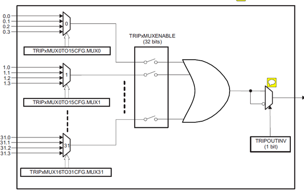
This is the the architecture of EPWMXBAR, In  this architecture All muxes which are enabled will be logically OR’d before being passed on to the respective TRIPx signal on the ePWM. But my questions is the function of OR’d.

I think the purpose of the OR’d is expand the source to trip the EPWM Trip-Zone submodule

(for eg,there is 5 external faults,we can set the epwmxbar register TRIP4 correspond to this 5 external faults,

EPwmXbarRegs.TRIP4MUX0TO15CFG.bit.Mux1 = 1; //inputxbar1 trip
EPwmXbarRegs.TRIP4MUX0TO15CFG.bit.Mux3 = 1; //inputxbar2 trip
EPwmXbarRegs.TRIP4MUX0TO15CFG.bit.Mux5 = 1; //inputxbar3 trip
EPwmXbarRegs.TRIP4MUX0TO15CFG.bit.Mux7 = 1; //inputxbar4 trip
EPwmXbarRegs.TRIP4MUX0TO15CFG.bit.Mux9 = 1;

)

So If there is one fualt happend we can blockade the pwm.

But if we want use this functions We must set  the fault signals status  "L" is represent normal ,and "H" is fault . But in most case The  "H" is represent normal ,and "L" is fault(for eg IPM's fault is "L").So in this case we can't use the or'd to expand the source to blockade the pwm.

My questions is in the  above case how to expand the source to blockade the pwm? In the EPWMXBAR architecture why is "OR'd" why not "AND'd"(we can set the normal status of CmpssH and CmpssL is "H" so we can use  "AND'd" instead  "OR'd")?

Thank you for your answer.

Regard 

shook.

  • Shook,

    it was or'd so that you can easily trip on anyone of many signals.

    "

    But if we want use this functions We must set  the fault signals status  "L" is represent normal ,and "H" is fault . But in most case The  "H" is represent normal ,and "L" is fault(for eg IPM's fault is "L").So in this case we can't use the or'd to expand the source to blockade the pwm.

    "

    If I am understanding you correctly, the quote above is not true, you can use this signal. Please look at the Technical Reference Manual. The PWM Chapter should help you, make sure to read the register field descritption for "DCAEVT1", "DCAEVT2", "DCBEVT1", and "DCBEVT2". These can be programmed to look for a "low" or a "high" signal coming from this or gate.

    Does that answer your question?

    Regards,
    Cody

  • Shook,
    Are you still having trouble?
    Regards,
    Cody
  • hi, cody
    I have resolved the issue. I didn't change my logic of the systerm. but after the outsid signal come into the GPIO, I invert the signal throgh the GpioCtrlRegs.GPDINV.bit.GPIO107 = 1. SO the result is right.
    thank you
    regards
    shook