This thread has been locked.

If you have a related question, please click the "Ask a related question" button in the top right corner. The newly created question will be automatically linked to this question.

CCS/LAUNCHXL-F28069M: ePWM, ADC, Required Interrupts

Part Number: LAUNCHXL-F28069M

Tool/software: Code Composer Studio

Hi, you all, this is Mike, I read this and I think I'm envolved in the same problem, I want to use the EPWM or th ECAP module to sync the Adc SOC, Somebody, here in the e2e forum, told me about a forced soc in the interrupt of the ECAP, but I'm not able to get a decent signal at all, Can I use ecap to sync the epwm in order to use this epwm to adcsoc

Best Regards, Mike

  • Using the ePWM to trigger the SOC is easiest since it can be done in hardware (no software force of a conversion required like there would be with eCAP). The adc_temp_sensor example for the F2806x uses the ePWM to trigger a conversion if you want some example code to look at.

    Would that work for you? I'm not understanding why you're thinking you should use the eCAP...? Can you explain the situation in a bit more detail?

    Thanks,
    Whitney
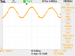
  • Hi Whitney, I have been working with some settings like it is shown in the adc_temp_sensor. Here it is How is displayed.

    And this is the input. 

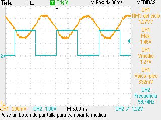
    As you see there is some distortion of the wave form.  This signal gets more distorted if I change frequency, I actually know (except I'm wrong) this distortion can be done by the nature of the circular buffer, also because  I have not adjust TBPRD and CMPA values for some values near to the frequency of the signal. But that is the trick. In my application I will be measuring the output signal coming from an air generator turbine. And the frequency of the waveform is not estable at all, so That's why I was thinking in use ECAP, because to that signal (shown above) I made a zero crossing circuit. 

    This is the waveforms


    And I want to use the square signal to sync my SOC, in order to improve my measurement..

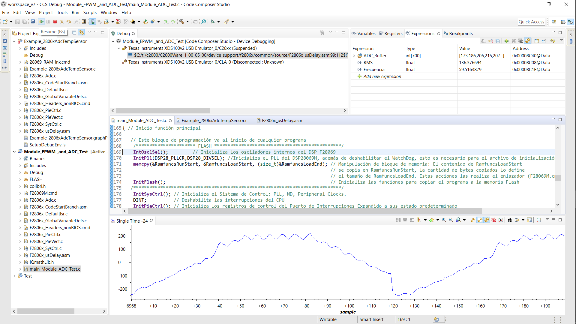
    This next Image is the signal I see with the code I'm making (THE CODE IS DOWN THERE).

    Thanks

    Mike

    I will share to you this code, Which actually I'm working with.

    #include "libreria.h"
    Uint32 PwmDuty;
    Uint32 PwmPeriod;
    _iq Periodo;
    _iq Frecuencia;
    /* Declaración de variables Globales*/
    long ADC_1;
    int16 ADC_Buffer[700];
    int32 ADC_Buffer2[700];
    _iq ADC_Buffer3;
    _iq ADC_Buf_Sum;
    _iq ADC_Buffer4;
    int32 ADC_BufferVDC;
    _iq ADC_Buff_VDC2;
    _iq RMS;
    _iq RMS1;
    _iq RMS2;
    _iq RMS3;
    _iq rms;
    _iq DC;
    _iq DC_ERROR;
    _iq DC1;
    Uint16 conv;
    Uint16 cont;
    Uint16 i;
    Uint16 zc;
    float freq;
    Uint16 zcmac;
    
    __interrupt void adc_isr(void);
    __interrupt void ecap_isr(void);
    //#define Device_cal (void   (*)(void))0x3D7C80
    
    
    void frecuencia(void)
       {
           EALLOW;                                     //Emulación de registros
           SysCtrlRegs.PCLKCR1.bit.ECAP1ENCLK = 1;     // SYSCLKOUT para habilitar eCAP1
           // Se inicia el módulo ECAP para medir el periodo y el ancho de pulso de una señal.
           ECap1Regs.ECEINT.all = 0;                   // Deshabilita todas las interrupciones del módulo eCAP
           ECap1Regs.ECCTL1.bit.CAPLDEN = 0;           // Deshabilita la carga de los resultados de captura
           ECap1Regs.ECCTL2.bit.TSCTRSTOP = 0;         // Detiene el contador
           ECap1Regs.TSCTR = 0;                        // Limpia el contador
           ECap1Regs.CTRPHS = 0;                       // Limpia el registro de contador de fase
           ECap1Regs.ECCTL2.bit.CAP_APWM = 0;          // Modo Captura
           ECap1Regs.ECCTL2.bit.SWSYNC = 1;            // Sincronización forzada del contador por software, sincroniza todas las bases de tiempo del ECAP
           ECap1Regs.ECCTL2.bit.SYNCO_SEL = 10;        // Syncin = Syncout, requerido por SWSYNC
           ECap1Regs.ECCTL2.bit.SYNCI_EN = 1 ;          // Deshabilita sincronización de entrada
           ECap1Regs.ECCTL2.bit.TSCTRSTOP = 1;         // Time Stamp Counter free-running
           ECap1Regs.ECCTL2.bit.REARM = 0;             // No Re-arme (Re-arme ->arma una secuencia de captura predeterminada)
           ECap1Regs.ECCTL2.bit.STOP_WRAP = 11;        // Toma 4 capturas en modo continuo
           ECap1Regs.ECCTL2.bit.CONT_ONESHT = 0;       // Operando en modo continuo
           ECap1Regs.ECCTL1.bit.FREE_SOFT= 11;         // Time Stamp Counter no es afectado por le emulación suspendida
           ECap1Regs.ECCTL1.bit.PRESCALE = 00000;      // Dividido entre 1
           ECap1Regs.ECCTL1.bit.CAPLDEN = 1;           // Habilita los registros de carga CAP1-4 en un evento
           ECap1Regs.ECCTL1.bit.CTRRST4 = 0;           // Sin reset en la primera captura
           ECap1Regs.ECCTL1.bit.CAP4POL = 1;           // Captura en el ascenso de la señal
           ECap1Regs.ECCTL1.bit.CTRRST3 = 0;           // Sin reset en la segunda captura
           ECap1Regs.ECCTL1.bit.CAP3POL = 0;           // Captura en el descenso de la señal
           ECap1Regs.ECCTL1.bit.CTRRST2 = 0;           // Sin reset en la tercera captura
           ECap1Regs.ECCTL1.bit.CAP2POL = 1;           // Captura en el ascenso de la señal
           ECap1Regs.ECCTL1.bit.CTRRST1 = 0;           // Sin reset en la cuarta captura
           ECap1Regs.ECCTL1.bit.CAP1POL = 0;           // Captura en el descenso de la señal
                     // Habilita la emulación de registros
           PieVectTable.ECAP1_INT = &ecap_isr;          // El contenido del subprograma de interrupción "ecap_isr" es copiado por el subprograma de interrupción "ECAP1_INT" contenido en la tabla.
           ECap1Regs.ECEINT.all = 0x0008;              // Habilita las interrupciones
           PieCtrlRegs.PIEIER4.bit.INTx1 = 1;          // Habilita la interrupción de ECAP1_INT en PIE grupo 4
           IER |= 0x0008;                              // Habilita INT4 en IER para habilitar el grupo 4 del bloque de interrupciones
           EINT;
           ERTM;
           GpioCtrlRegs.GPACTRL.all  = 0x00000000;
           GpioCtrlRegs.GPAMUX2.bit.GPIO24 = 1;        // GPIO 24 Configurador para captura de pulsos
           GpioCtrlRegs.GPADIR.bit.GPIO24 = 0;         // GPIO 24 como entrada
           GpioCtrlRegs.GPAPUD.bit.GPIO24 = 0;         // Pull-up habilitado para GPIO24 (0)
           //GpioCtrlRegs.GPAPUD.bit.GPIO24 = 1;         // Pull-up deshabilitado para GPIO24 (1)
           EDIS;
       }
    
    void voltaje_rms(void)
    {
        for(i=0;i<701;i++)                     // Ciclo for para inicializar ADC_Buffer con un arreglo de 0's
        {
            ADC_Buffer[i]=0;
        }
        for(i=0;i<701;i++)                     // Ciclo for para inicializar ADC_Buffer2 con un arreglo de 0's
          {
              ADC_Buffer2[i]=0;
          }
        EALLOW;                          // Habilita la emulación de registros
        PieVectTable.ADCINT1 = &adc_isr; // El contenido del subprograma de interrupción "adc_isr" es copiado por el subprograma de interrupción "ADCINT1" contenido en la tabla.
        InitAdc();                       // Inicializa el módulo del ADC
        AdcOffsetSelfCal();              // Ajuste de offset del ADC debido a su construcción
        (*Device_cal)();                 // Ajuste de error de ganancia debido a la construcción del ADC
        PieCtrlRegs.PIEIER1.bit.INTx1 = 1;// Habilita la Interrupción 1.1 en el Puerto de expansión de interrupciones
        IER |= M_INT1;                   // Habilita la interrupción 1 del CPU
        EINT;                            // Habilita las interrupciones globales
        ERTM;                            // Habilita las interrupciones en tiempo real
        EDIS;                            // Deshabilita la emulación de registros
        conv=0;                          // Variable auxiliar que define, temporalmente, la longitud del Buffer
        EALLOW;                                // Habilita la emulación de registros
        //EPwm1Regs.TBCTL.bit.PHSEN = 1;
        GpioCtrlRegs.AIOMUX1.bit.AIO10 = 2;    // GPIO 26 habilitado para funciones Analógicas
        AdcRegs.ADCCTL2.bit.ADCNONOVERLAP = 1; // Habilita el modo de sobrelapamiento de muestras
        AdcRegs.ADCCTL1.bit.INTPULSEPOS = 1;   // Control de pulso generador de interrupción -> 0 = Inicio de conversión, 1 = Un ciclo por resultado
        AdcRegs.INTSEL1N2.bit.INT1E = 1;       // Habilita ADCINT1
        AdcRegs.INTSEL1N2.bit.INT1CONT = 0;    // Modo de interrupciones continuas deshabilitado -> 0= Pulso generado si la bandera es limpiada por SW, 1=Pulso generado cada EOC
        AdcRegs.INTSEL1N2.bit.INT1SEL = 1;     // Final de conversion 1 (EOC 1) es el disparo (trigger) de ADCINT1
    
        AdcRegs.ADCSOC0CTL.bit.CHSEL = 10;      // Inicio de conversión 0 (SOC) para el canal ADCINB2 (pin 26)
        AdcRegs.ADCSOC0CTL.bit.TRIGSEL = 5;    // ePWM 1 es el disparo para SOC1
        AdcRegs.ADCSOC0CTL.bit.ACQPS = 8;      // Ventana de Sample/Holding a 10 ciclos del reloj del ADC
    
        AdcRegs.ADCSOC1CTL.bit.CHSEL = 10;      // Inicio de conversión 0 (SOC) para el canal ADCINB2 (pin 26)
        AdcRegs.ADCSOC1CTL.bit.TRIGSEL = 5;    // ePWM 1 es el disparo para SOC1
        AdcRegs.ADCSOC1CTL.bit.ACQPS = 8;      // Ventana de Sample/Holding a 10 ciclos del reloj del ADC
    
        AdcRegs.ADCSOC2CTL.bit.CHSEL = 10;      // Inicio de conversión 0 (SOC) para el canal ADCINB2 (pin 26)
        AdcRegs.ADCSOC2CTL.bit.TRIGSEL = 5;    // ePWM 1 es el disparo para SOC1
        AdcRegs.ADCSOC2CTL.bit.ACQPS = 8;      // Ventana de Sample/Holding a 10 ciclos del reloj del ADC
    
    
        AdcRegs.ADCSOC3CTL.bit.CHSEL = 10;      // Inicio de conversión 0 (SOC) para el canal ADCIN1 (pin 26)
        AdcRegs.ADCSOC3CTL.bit.TRIGSEL = 5;    // ePWM 1 es el disparo para SOC1
        AdcRegs.ADCSOC3CTL.bit.ACQPS = 8;      // Ventana de Sample/Holding a 10 ciclos del reloj del ADC
       /* EPwm1Regs.ETSEL.bit.SOCAEN   = 1;        // Enable SOC on A group
        EPwm1Regs.ETSEL.bit.SOCASEL  = 4;        // Select SOC from from CPMA on upcount
        EPwm1Regs.ETPS.bit.SOCAPRD   = 1;        // Generate pulse on 1st event
        EPwm1Regs.CMPA.half.CMPA     = 0x0080;   // Set compare A value
        EPwm1Regs.TBPRD              = 0xFFFF;   // Set period for ePWM1
        EPwm1Regs.TBCTL.bit.CTRMODE  = 0;   */     // count up and start
        EPwm1Regs.TBCTL.bit.CTRMODE = 0x3;     // Deshabilita el Temporizador
        EPwm1Regs.TBCTL.all = 0xC033;
        EPwm1Regs.TBCTR = 0x0000;              // Limpia el contador del temporizador
        EPwm1Regs.TBPRD = 10416;
        EPwm1Regs.TBPHS.half.TBPHS = 0x0000;    // Configura la fase del temporizador
        EPwm1Regs.ETSEL.bit.SOCAEN = 1;        // Selección de registros para Eventos de Disparo -> Disparos en SOC A habilitados
        EPwm1Regs.ETSEL.bit.SOCASEL = 4;       // Selección de SOC en la comparación del contador ascente de A
        EPwm1Regs.ETPS.bit.SOCAPRD = 1;        // Generación de SOC al primer evento
        EPwm1Regs.TBCTL.bit.CTRMODE = 0x0;
        asm(" EALLOW");                         // Enable EALLOW protected register access
        SysCtrlRegs.PCLKCR0.bit.TBCLKSYNC = 1;  // TBCLK to ePWM modules enabled
        asm(" EDIS");
    
        }
    
    void main(void)
    { // Inicio función principal
    
       // Este bloque de programación va al inicio de cualquier programa
        /********************** FLASH ***********************************************/
        IntOsc1Sel();         // Inicializa los osciladores internos del DSP F28069
        InitPll(DSP28_PLLCR,DSP28_DIVSEL); //Inicializa el PLL del DSP28069M, además de deshabilitar el WatchDog, esto es necesario para el archivo de inicialización "F2806x_CodeStartBranch.asm"
        memcpy(&RamfuncsRunStart, &RamfuncsLoadStart, (size_t)&RamfuncsLoadEnd); // Manipulación de bloque de memoria: El contenido de RamfuncsLoadStart
                                                                                 // se copia en RamfuncsRunStart, la cantidad de bytes copiados lo define
                                                                                 // el tamaño de RamfuncsLoadEnd. Estas acciones las realiza el enlazador (F28069M.cmd)
        InitFlash();                                                             // Inicializa las funciones para copiar el programa a la memoria Flash
       /*****************************************************************************/
        InitSysCtrl(); // Inicializa el Sistema de Control: PLL, WD, Peripheral Clocks.
        DINT;          // Deshabilita las interrupciones del CPU
        InitPieCtrl(); // Inicializa los registros de control del Puerto de Interrupciones Expandido a sus estado predeterminado
        IER = 0X0000;  // Deshabiita las interrupciones del CPU
        IFR = 0X0000;  // Limpia las banderas de interrupción del CPU
        InitPieVectTable(); //Inicializa la tabla de arreglos de interrupción, las interrupciones utilizadas son remapeadas en esta función
        frecuencia();
        voltaje_rms();
    
    
        GpioCtrlRegs.GPBMUX1.bit.GPIO39 = 0;   // MUX -> GPIO
        GpioDataRegs.GPBCLEAR.bit.GPIO39 = 1;  // Salida en estado bajo antes de configurar el pin como Salida, Modo Drenador (Sink). Consultar spruh18g.pdf (pág 120)
        GpioCtrlRegs.GPBDIR.bit.GPIO39 = 1;    // GPIO39 como salida
        EDIS;                                  // Deshabilita la emulación de registros/*
    
        for(;;)
       { // Inicio de For
            EALLOW;                                // Habilita la emulación de registros
            GpioDataRegs.GPBSET.bit.GPIO39 = 1;    // Pin Modo Fuente (Source) ó ALTO
            DELAY_US(100000);                      // Intervalo de tiempo de 0.1 s
            GpioDataRegs.GPBCLEAR.bit.GPIO39 = 1;  // Pin Modo Sumidero (Sink) ó LOW
            DELAY_US(100000);                      // Intervalo de tiempo de 0.1 s
            EDIS;                                  // Deshabilita la emulación de registros
       } // Fin de for
    
    
    } // Fin de función principal
    
    /* FIN DE "PROGRAMACIÓN EN LA FLASH" */
    
    __interrupt void
    adc_isr(void) // Inicio del programa de interrupción
    {
    
        ADC_Buffer[conv] = AdcResult.ADCRESULT3-0x0628;     // Cada espacio o localidad del arreglo es llenado con el resultado del registro AdcResult 1
        ADC_Buffer2[conv] = pow(ADC_Buffer[conv],2); /* VRMS Se eleva al cuadrado cada dato ingresado en el buffer */
        ADC_BufferVDC += ADC_Buffer[conv];           /* VDC  Se hace una suma de todos los datos ingresados en el buffer*/
        ADC_Buf_Sum += ADC_Buffer2[conv];            /* VRMS Se hace una suma de todos los datos elevados al cuadrado que ingresaron al buffer*/
        if (conv == 699)                             // Si la variable conv si es igual a la longitud del buffer menos uno realiza los algoritmos de VDC y VRMS y despues se reinicia
        {
            ADC_Buffer3 = ADC_Buf_Sum/conv+1.0;     /* VRMS La suma de los datos elevados al cuadro del ADC es divida entre la longitud del buffer */
            ADC_Buff_VDC2 = ADC_BufferVDC/conv+1.0; /* VDC  La suma de los datos del ADC es divida entre la longitud del buffer */
            DC = (3.3*ADC_Buff_VDC2)/4096.0;          /* VDC  Se multiplica el promedio de los datos por un factor de conversión y se tiene el valor DC de la señal muestreada */
            //DC_ERROR=DC1-1.29;
            //DC=DC1-DC_ERROR;
            ADC_Buffer4 = sqrt(ADC_Buffer3);      /* VRMS Se obtiene la raíz cuadrada de la división (Sumatoria/Longitud_Buffer) */
            RMS=ADC_Buffer4*(3.3/4096.0)*1060.0;           /* VRMS Se multiplica el resultado de la raíz cuadrada por el factor de conversión y se obtiene el valor RMS de la señal muestreada */
            conv = 0.0;                             /* El contador auxiliar del buffer se reinicia */
            ADC_BufferVDC=0.0;                      /* El contenido de la suma de todos los datos del buffer se iguala a cero, con el fin de evitar sobrelapamiento de datos */
            ADC_Buf_Sum = 0.0;                       /* El contenido de la suma del cuadrado de todos los datos del buffer se iguala a cero, con el fin de evitar sobrelapamiento de datos */
        } //Realización del voltaje de OFFSET
        else                                      // Si la variable conv no es igual a la longitud del buffer menos uno entonces incrementa en uno
        {
            conv++;
        }
        AdcRegs.ADCINTFLGCLR.bit.ADCINT1 = 1;     // Limpia la bandera de interrupción del ADC
        PieCtrlRegs.PIEACK.all = PIEACK_GROUP1;   // El bloque de expandido de interrupción de perifericos reconoce una interrupción en el grupo 1
        //return;
    
    } // Fin del subprgrama de interrupción
    
    __interrupt void
    ecap_isr(void)
    {
    
          PieCtrlRegs.PIEACK.all = PIEACK_GROUP4;     // Debe reconocer el grupo PIE
          ECap1Regs.ECCLR.bit.INT = 1;                // Limpia l bandera de interrupción de ECAP1
          ECap1Regs.ECCLR.bit.CEVT3 = 1;              // Limpia l bandera de CEVT3
      // Calcula el ciclo de trabajo (flanco ascendente a flanco descendente)
      //   PwmDuty = (int32)ECap1Regs.CAP2 - (int32)ECap1Regs.CAP1;
      // Calcula el periodo  (flanco ascendente a flanco ascendente)
          PwmPeriod = (int32)ECap1Regs.CAP3 - (int32)ECap1Regs.CAP1 ;
          Periodo = (PwmPeriod/90401640.0);
          Frecuencia = 1/Periodo;
    }


  • I was so confused, but I found a solution to this, checking on the firmware snipets in spruh18g.pdf I was using some epwm registers to compare TBPRD, then the Start of Conversion, this compare was so little, and I was breaking what Nyquist said.