This thread has been locked.

If you have a related question, please click the "Ask a related question" button in the top right corner. The newly created question will be automatically linked to this question.

TMS320F28335: LED blinks in stand alone status

Part Number: TMS320F28335
Other Parts Discussed in Thread: C2000WARE

Hi, 

I am using the TMS320F28335 board, and when I put the LED blinking code on the flash and run it after debugging, the LED blinks well.

I want to check the stand alone status, but it doesn't work.
How can I check the led blink with stand alone?

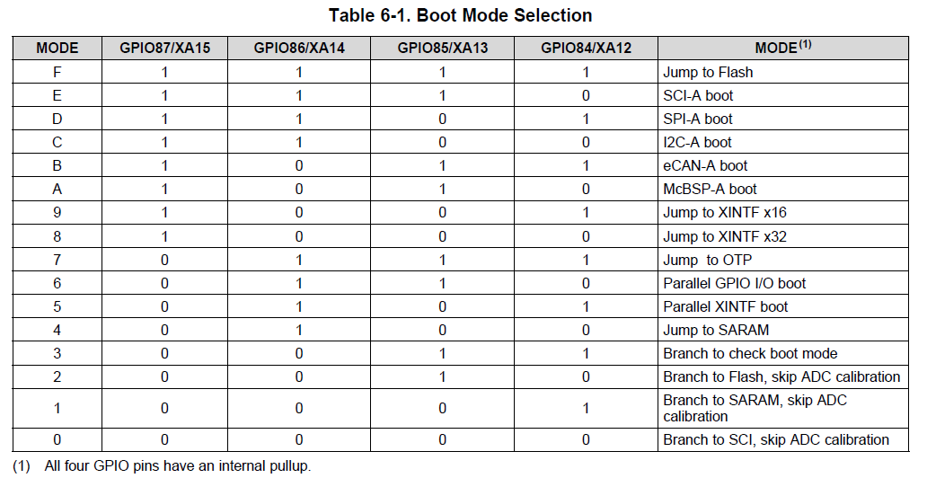
The boot mode is set to jump to flash, and the process of checking the led blinking on the stand alone is as follows.

CCS Shutdown, Board Off, XDS100v2 Cable Remove, XDS100v2 Cable Connection, Board On.

There is no response to the LED.


To power the TMS320F28335, the only option is the XDS100V2 cable.

Thanks, Han

  • Hi Han,

    Are you using the timed LED blink example from c2000ware?

    C:\ti\c2000\C2000Ware_2_00_00_03\device_support\f2833x\examples\timed_led_blink

    What changes have you made to the project to make it run standalone from flash? By default the example is configured to run from RAM.

    See this App Report for running code from flash:

    http://www.ti.com/lit/spra958

    Best,

    Kevin

  • I'm using LED flashing, the default environment for uC / OS-II provided by Mirium.
    Just use the link command file as an example provided by TI for run in Flash.

    The link command file is as follows:


    MEMORY
    {
    PAGE 0: /* Program Memory */
    /* Memory (RAM/FLASH/OTP) blocks can be moved to PAGE1 for data allocation */

    //BEGIN_Flash : origin = 0x33FFF6, length = 0x000002
    // ZONE0 : origin = 0x004000, length = 0x001000 /* XINTF zone 0 */
    RAML0 : origin = 0x008000, length = 0x001000 /* on-chip RAM block L0 */
    RAML1 : origin = 0x009000, length = 0x001000 /* on-chip RAM block L1 */
    RAML2 : origin = 0x00A000, length = 0x001000 /* on-chip RAM block L2 */
    RAML3 : origin = 0x00B000, length = 0x001000 /* on-chip RAM block L3 */
    ZONE6 : origin = 0x0100000, length = 0x100000 /* XINTF zone 6 */
    ZONE7A : origin = 0x0200000, length = 0x00FC00 /* XINTF zone 7 - program space */
    FLASHH : origin = 0x300000, length = 0x008000 /* on-chip FLASH */
    FLASHG : origin = 0x308000, length = 0x008000 /* on-chip FLASH */
    FLASHF : origin = 0x310000, length = 0x008000 /* on-chip FLASH */
    FLASHE : origin = 0x318000, length = 0x008000 /* on-chip FLASH */
    FLASHD : origin = 0x320000, length = 0x008000 /* on-chip FLASH */
    FLASHC : origin = 0x328000, length = 0x008000 /* on-chip FLASH */
    FLASHA : origin = 0x338000, length = 0x007F80 /* on-chip FLASH */
    CSM_RSVD : origin = 0x33FF80, length = 0x000076 /* Part of FLASHA. Program with all 0x0000 when CSM is in use. */
    BEGIN : origin = 0x33FFF6, length = 0x000002 /* Part of FLASHA. Used for "boot to Flash" bootloader mode. */
    CSM_PWL : origin = 0x33FFF8, length = 0x000008 /* Part of FLASHA. CSM password locations in FLASHA */
    OTP : origin = 0x380400, length = 0x000400 /* on-chip OTP */
    ADC_CAL : origin = 0x380080, length = 0x000009 /* ADC_cal function in Reserved memory */

    IQTABLES : origin = 0x3FE000, length = 0x000b50 /* IQ Math Tables in Boot ROM */
    IQTABLES2 : origin = 0x3FEB50, length = 0x00008c /* IQ Math Tables in Boot ROM */
    FPUTABLES : origin = 0x3FEBDC, length = 0x0006A0 /* FPU Tables in Boot ROM */
    ROM : origin = 0x3FF27C, length = 0x000D44 /* Boot ROM */
    RESET : origin = 0x3FFFC0, length = 0x000002 /* part of boot ROM */
    VECTORS : origin = 0x3FFFC2, length = 0x00003E /* part of boot ROM */

    PAGE 1 : /* Data Memory */
    /* Memory (RAM/FLASH/OTP) blocks can be moved to PAGE0 for program allocation */
    /* Registers remain on PAGE1
    */

    // 내가 넣은것
    FLASH_REGS : origin = 0x000A80, length = 0x000060 /* FLASH registers */
    PIE_VRAM : origin = 0x000D00, length = 0x000100

    BOOT_RSVD : origin = 0x000000, length = 0x000050 /* Part of M0, BOOT rom will use this for stack */
    RAMM0 : origin = 0x000050, length = 0x0003B0 /* on-chip RAM block M0 */
    RAMM1 : origin = 0x000400, length = 0x000400 /* on-chip RAM block M1 */
    RAML4 : origin = 0x00C000, length = 0x001000 /* on-chip RAM block L1 */
    RAML5 : origin = 0x00D000, length = 0x001000 /* on-chip RAM block L1 */
    RAML6 : origin = 0x00E000, length = 0x001000 /* on-chip RAM block L1 */
    RAML7 : origin = 0x00F000, length = 0x001000 /* on-chip RAM block L1 */
    ZONE7B : origin = 0x20FC00, length = 0x000400 /* XINTF zone 7 - data space */
    FLASHB : origin = 0x330000, length = 0x008000 /* on-chip FLASH */
    }

    /* Allocate sections to memory blocks.
    Note:
    codestart user defined section in DSP28_CodeStartBranch.asm used to redirect code
    execution when booting to flash
    ramfuncs user defined section to store functions that will be copied from Flash into RAM
    */

    SECTIONS
    {

    /* Allocate program areas: */
    /* The Flash API functions can be grouped together as shown below.
    The defined symbols _Flash28_API_LoadStart, _Flash28_API_LoadEnd
    and _Flash28_API_RunStart are used to copy the API functions out
    of flash memory and into SARAM */

    Flash28_API:
    {
    -lFlash28335_API_V210.lib(.econst)
    -lFlash28335_API_V210.lib(.text)
    } LOAD = FLASHD,
    RUN = RAML0,
    LOAD_START(_Flash28_API_LoadStart),
    LOAD_END(_Flash28_API_LoadEnd),
    RUN_START(_Flash28_API_RunStart),
    PAGE = 0

    .cinit : > FLASHA PAGE = 0
    .pinit : > FLASHA, PAGE = 0
    .text : > FLASHA PAGE = 0
    ram_start : > BEGIN PAGE = 0
    ramfuncs : LOAD = FLASHD,
    RUN = RAML0,
    LOAD_START(_RamfuncsLoadStart),
    LOAD_END(_RamfuncsLoadEnd),
    RUN_START(_RamfuncsRunStart),
    PAGE = 0

    csmpasswds : > CSM_PWL PAGE = 0
    csm_rsvd : > CSM_RSVD PAGE = 0
    /*내거 넣은것 */
    FlashRegsFile : > FLASH_REGS, PAGE = 1
    .cio : > RAML4, PAGE = 1
    pie_vram : > PIE_VRAM, PAGE = 1

    /* Allocate uninitalized data sections: */
    .stack : > RAMM1 PAGE = 1
    .ebss : > RAML4 PAGE = 1
    .esysmem : > RAMM0 PAGE = 1

    /* Initalized sections go in Flash */
    /* For SDFlash to program these, they must be allocated to page 0 */
    .econst : > FLASHA PAGE = 0
    .switch : > FLASHA PAGE = 0

    /* Allocate IQ math areas: */
    IQmath : > FLASHC PAGE = 0 /* Math Code */
    IQmathTables : > IQTABLES, PAGE = 0, TYPE = NOLOAD
    IQmathTables2 : > IQTABLES2, PAGE = 0, TYPE = NOLOAD
    FPUmathTables : > FPUTABLES, PAGE = 0, TYPE = NOLOAD

    /* Allocate DMA-accessible RAM sections: */
    DMARAML4 : > RAML4, PAGE = 1
    DMARAML5 : > RAML5, PAGE = 1
    DMARAML6 : > RAML6, PAGE = 1
    DMARAML7 : > RAML7, PAGE = 1

    /* Allocate 0x400 of XINTF Zone 7 to storing data */
    ZONE7DATA : > ZONE7B, PAGE = 1

    /* .reset is a standard section used by the compiler. It contains the */
    /* the address of the start of _c_int00 for C Code. /*
    /* When using the boot ROM this section and the CPU vector */
    /* table is not needed. Thus the default type is set here to */
    /* DSECT */
    .reset : > RESET, PAGE = 0, TYPE = DSECT
    vectors : > VECTORS PAGE = 0, TYPE = DSECT

    /* Allocate ADC_cal function (pre-programmed by factory into TI reserved memory) */
    .adc_cal : load = ADC_CAL, PAGE = 0, TYPE = NOLOAD

    }

    -------------------------------------------------- -----------------------------


    When I run debugging, the LED blinks well. But when I reconnect after removing the JTAG port, nothing happens.

    I do not think that using uC / OS provided by Mirium does not work in Flash.

    When run with debugging, I think the commands in the text area in Flash are well executed.

    I just don't know how to check stand alone status after uploading to flash.

    Thanks, Han

  • Hi Han,

    OK, that linker command file looks fine. Few things you could be missing listed below:

    • Include DSP2833x_CodeStartBranch.asm in project from C2000ware:
      • C:\ti\c2000\C2000Ware_2_00_00_03\device_support\f2833x\common\source
    • May need to copy function from Flash to RAM in project. Use Memcpy function with Ramfuncs as arguments

    Best,

    Kevin

  • I made the addition as you said, and the code that uses the MemCopy function to get the code in Flash into RAM runs fine.
    Therefore, when running in debugging mode in CCS, the LEDs work well. But after turning off the power, I don't know why it doesn't run automatically.

    How do you make sure this board is running standalone?
    I'm using a Texas Instrumnets XDS100v2 USB Debug Probe with power, and I'm using an Experimenter's Kit-Delfino F28335.

    Is it right to run standalone in this environment?

  • Hi Han,

    Can you confirm what the state of your Boot Mode pins are? You can use SW2 on the ControlCard to set the state of these pins.

    All high is Jump to Flash. Several of the other modes should end up booting from FLASH as well, see the following for more info http://www.ti.com/lit/spru963

    Best,

    Kevin

  • Thanks, Kevin

    1 was written under SW2, so I thought Jump to Flash was low.
    Thanks, I confirmed it worked well.


    But can you tell me what 1 means under SW2?

    Regards, Han