This thread has been locked.

If you have a related question, please click the "Ask a related question" button in the top right corner. The newly created question will be automatically linked to this question.

CCS/LAUNCHXL-F28379D: emif_dc_flash,emif daughter card of LAUNCHXL-F28379D

Part Number: LAUNCHXL-F28379D
Other Parts Discussed in Thread: TMS320F28379D, C2000WARE

Tool/software: Code Composer Studio

I have designed a board wiht TMS320F28379D and connect a flash S29AL016J70TFI020.My design is based on TI's official design C2000Ware_2_00_00_02\boards\TIDesigns\F28379D_EMIF_DC.

The connection of my design between DSP and Flash is the same as the design of TI's.

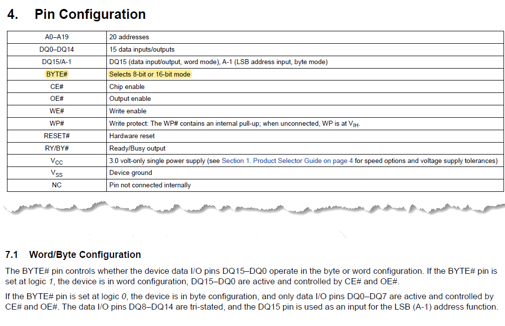
Now I have a question about the design. The picture below is part of the TI design of F28379D_EMIF_DC_SCH.pdf, the pin14 WP# and pin47 BYTE#  which are marked by red circle seem to be left unconnected.And in my design,I also left these two pins unconnected as well.I'm wondering whether my understanding of these two pins' connection are correct.And the mode of the flash decided by pin BYTE#  is byte or word?


  • user5876081,

    The BYTE and WP signals are not unconnected in the design; they are pulled up through the R13 and R14 resistors.  The red "X" is an Altium symbol that indicates that design warnings are being suppressed for the signal.

    You can refer to the memory datasheet to see the functional descriptions for all of the signals. 

    -Tommy

  • Dear Tommy,

    Thanks a lot for your answer.

    Now I have another question.Since I have left the pin BYTE# unconnected,I found that the flash could enter the CFI Query mode by writing the CFI Query command in WORD mode.But when I was tring to erase and program the flash also in the word mode by using  the emif_dc_flash example project provided by C2000Ware(C:\ti\c2000\C2000Ware_2_00_00_02\device_support\f2837xd\examples\cpu1\emif_dc_flash) ,but I failed to control the DQ15~DQ8. For example,after erasing the  flash,the data in the dataBuffer were all 0X00FF but not the expected 0XFFFF.

        //
        // Erase flash and verify buffer contents
        //
        EMIF_DC_eraseCS2Flash(EMIF_NUM);
    
        for(word=0; word<BUFFER_WORDS; word++)
        {
            if(dataBuffer[word] != 0xFFFF)
            {
                errors++;
                ESTOP0;
                break;
            }
        }
    

    When tring to write to flash ,I also encounter the same problem that can only operate on low 8bit.For example,when I were tring to write 0x0101 to an address, but the actual corresponding value in the address is 0x0001.

    So I am wondering whether the unconnection of BYTE# cause these problems.

    Thank you again for your help.

  • user5876081,

    I suspect that your issues are related to the uncontrolled BYTE# signal.  I recommend pulling the signal to VCC if you want to use the C2000Ware example.

    -Tommy