This thread has been locked.

If you have a related question, please click the "Ask a related question" button in the top right corner. The newly created question will be automatically linked to this question.

TMS320F2812: Glitch in the PWM signals

Part Number: TMS320F2812


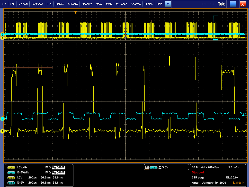
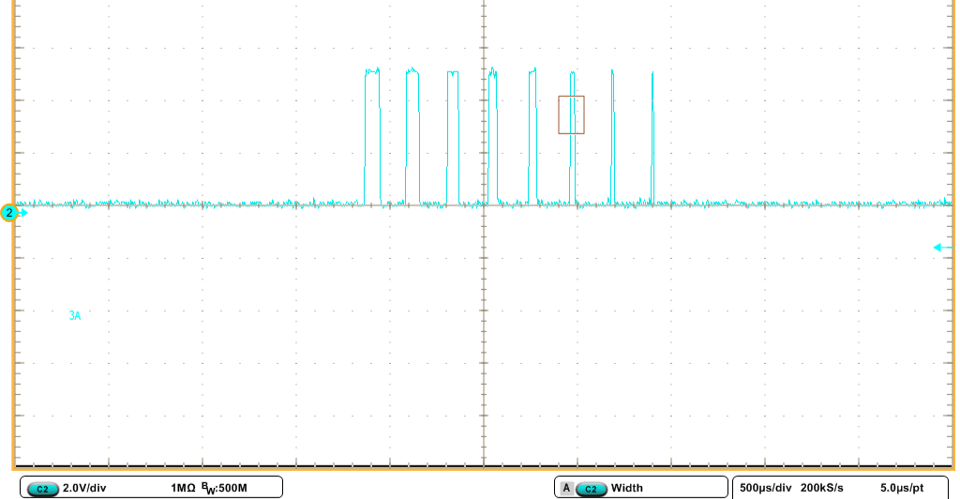
I am trying to give duty cycle ratio to the PWM channel 1. The duty cycle starts from 50% to 0 and it is supposed to stay off for half of fundamental cycle. In the last cycle before turning it off for half a cycle, the signal stays ON until the end of the period (Please see the picture). The blue signal is another PWM cycle with constant duty cycle. Here is my code:

rtb_Sum1 = 100U + rtDWork.UnitDelay1_DSTATE;


if (rtb_Sum1 > 4000U) {
rtb_Sum1 = 0U;
}

rtDWork.T1Ao = rtb_Sum1;

%keeps the signal off for higher duty cycles
if (rtb_Sum1 < 2000U) {
rtDWork.T1Ao = 4000U;
}

{
EvaRegs.CMPR1 = (uint16_T) (rtDWork.T1Ao / 2);
EvaRegs.CMPR2 = (uint16_T) (1638U / 2);
EvaRegs.CMPR3 = (uint16_T) (1638U / 2);
EvaRegs.ACTRA.all = 1638U;
}

rtDWork.UnitDelay1_DSTATE = rtb_Sum1;

  • MarziPan,

    thanks for the question! Can you please describe how the PWM is being toggled on and off? Are you using CTR = ZRO or PRD to trigger an action? Are you using CMPA or CMPB to set or clear the PWM?

    Thanks,
    Cody 

  • Thanks for replying to my question.

    I have been using Simulink blocks. I am using CMPA. Compare Control Register is set to 0xA600 which makes the reload condition on underflow or period match.

  • I tried 0xC600 for COMCONA. The issue with the narrowest pulse width gets resolved but the pulses with longer width arbitrarily become zero. 

  • Are you calling "CMPCTL" the Compare Control Register?

    What is COMCONA, I am unfamiliar with this register?

    I apologize I am not adept at debugging Simulink code, we will need to talk in terms of C2000 features. What are you using to set the PWM output high, and what are you using the set the PWM output low?

     are you familiar with this issue happening in Simulink generated code?


    Regards,
    Cody 

  • Hi,

    We can take this forward from MathWorks Support. We need your model and may need to host WebEx meetings.

  • I used spru065e document to understand the registers for PWM. I hope it is the right document. Page 58 has all the registers. ACTRA is set to support active high. CMPRx includes the duty ratio in number of cycles and is set in each sampling time. COMCON is set to A600 by the simulink but I can change it in the code. T1CON is set to  0x1042. 

  • Hello Venkatesh,

    Where should I send my models to you? Should I ask the question in MathWorks?

  • HI MarziPan,

    The best/fastest option is to directly contact MathWorks Tech Support,. They will likely ask for your model to review.

    Cheers,

    -Brian

  • Hello Brian,

    Can I follow up here in terms of C2000 features as well?

    Regards,

  • Hi MarziPan,

    I can take feature feedback and provide to Development team for their review. I may or may not be able to comment on future plans / features.

    Cheers,

    -Brian

  • MarziPan,

    yes please feel free to follow up here with c2000 specific questions.

    I apologize that I didn't recognize the naming. After F2812 the naming convention for these registers changed.

    I will take a look at these registers and reply if I find anything wrong with your configuration. In the mean time, the MathWorks guys should be able to support this issue.

    Regards,
    Cody 

  • Thank you Cody. I also could not find any example codes for F2812 PWM. Is there a DSP similar to it that has examples on TI websites?

  • Example software can be found on the product page.

    Here is a shortcut: http://www.ti.com/lit/zip/SPRC097?jktype=tools_software 

    Regards,
    Cody 

  • Thanks for sending the link to me. Can I send my CCS project to you to see if the same thing happens in your device as well?

  • MarziPan,

    I do not think this is a 1 off device defect, so I suspect that the outcome will be the same if I test it on my end.

    Do you have the setup code for the PWM? I can review that, and it may explain what is going on here.

    Regards,
    Cody 

  • Thanks for considering my request. I have the setup code. How can I send it to you? I appreciate your time.

  • Can you share the code here or is it confidential? You should be able to add a small code code snippet using the button with the following symbol"</>". If its a bit longer then maybe attach it as a file, but all i need is the setup code so I expect it to be pretty short.

    Regards,
    Cody 


  • PWM settings:

    void config_PWM_A(uint16_T timerPeriod, uint16_T waveformType, uint16_T unit1Status, char* unit1Source, uint16_T unit1Value, uint16_T unit2Status, char* unit2Source, uint16_T unit2Value, uint16_T unit3Status, char* unit3Source, uint16_T unit3Value, uint16_T controlLogic, uint16_T enableDeadband1, uint16_T enableDeadband2, uint16_T enableDeadband3, uint16_T deadbandPrescaler, uint16_T deadbandPeriod, uint16_T timerToADC, uint16_T preScaler) { const uint16_T DISABLED= 0; /* Initalize EVA Timer1 which controls PWM1-PWM6 */ EvaRegs.T1PR = timerPeriod; /* period*/ EvaRegs.T1CNT = 0x0000; /* counter*/ EvaRegs.T1CON.all = 0x1042; /* enable; compare enable; default TMODE */ EvaRegs.T1CON.bit.TMODE = waveformType;/* adjust Timer TMODE*/ EvaRegs.T1CON.bit.TPS = preScaler; /* Input clock prescaler*/ /* Set ADC SOC signal according to user's request */ EvaRegs.GPTCONA.bit.T1TOADC = timerToADC; /* Enable compare for PWM1-PWM6 */ EvaRegs.CMPR1 = unit1Status ? unit1Value : DISABLED; EvaRegs.CMPR2 = unit2Status ? unit2Value : DISABLED; EvaRegs.CMPR3 = unit3Status ? unit3Value : DISABLED; /* Compare action control: Action that takes place on a compare event */ EvaRegs.ACTRA.all = controlLogic; EvaRegs.DBTCONA.bit.EDBT1 = enableDeadband1; EvaRegs.DBTCONA.bit.EDBT2 = enableDeadband2; EvaRegs.DBTCONA.bit.EDBT3 = enableDeadband3; EvaRegs.DBTCONA.bit.DBT = deadbandPeriod; EvaRegs.DBTCONA.bit.DBTPS = deadbandPrescaler; EvaRegs.COMCONA.all = 0xA600; }

    Initialization:

    GpioMuxRegs.GPAMUX.all |= 63U; /* EVA PWM 1-6 pins*/
    config_PWM_A (1172.0,1,1,"INPUT_PORT",0.0,
    1,"INPUT_PORT",0.0,1,"INPUT_PORT",0.0,0,
    1, 1, 1, 4, 10, 0, 2);

    During function call EvaRegs.CMPR1, EvaRegs.CMPR2 and EvaRegs.CMPR3 are set.

    EvaRegs.ACTRA.all is set to 1638U.

    I could remove the glitch by these registers but I am not sure if it makes the longer duty ratios wrong or not:

    if( rtDWork.Merge10 > 4000 && rtDWork.Merge10 <4688)

         { EvaRegs.COMCONA.all = 0x8200;  }

         else

         { EvaRegs.COMCONA.all = 0xA600;}

  • MarziPan,

    I can see the following points in the current PWM configuration:

    1. CMPA register is updated at every PWM period to change the duty cycle of the PWM.
    2. CMPA value is set to 4000 cycles to achieve 0% duty cycle.
    3. Up-down count mode is used. That means, PWM is turned on when (counter=CMPA on up direction) and PWM is turned off when (counter=CMPA on down direction).
    4. Compare register reload with new values is set to the event when (counter = period) or (counter = 0) event. (COMCONA register = 0xA600)
    So what exactly happens when the glitch appears is the following
    1. The shadow register for compare is updated with new value of 4000 when PWM counter is in up direction.
    2. The active register still holds old compare value of 3800. Hence the PWM is turned on when the counter reaches 3800 on up direction.
    3. When PWM reaches 4000, the active compare register is loaded with the new value from shadow register (4000). (As set in COMCONA register)
    4. The counter starts the down direction decrementing to 0. In this case it will never find any match to current active compare register value of 4000. Hence PWM is kept on till it reaches next cycle PWM compare match of 4000. Here it will turn off the PWM. Hence you will see the duty cycle is set to 50% when it was supposed to be 0.
    You will see this issue intermittently when the new compare value of 4000 is loaded on (counter=period) event. You will not see this issue when the new compare value of 4000 is loaded at (counter=0) event.
      
    What you can try in this case to solve the problem is to change the value of CLD1-CLD0 fields of COMCONA register to set the compare reload condition to (counter=0) event only or (immediate) event.
      
    Thanks,
    Aditya
  • MarziPan,

    the issue that Aditya is describing is reasonably common. Please let me know if changing your load event fixed your issue.

    Regards,
    Cody 

  • Hello Aditya,

    Thanks for looking at my code very detailed. I have changed the CLD1-CLD0 to immediately. It fixes the issue at the pulses with low width but it causes anomalies in the pulses with larger width. I tried the same code this time with bigger time steps and therefore lower number of pulses. This is what all the pulse series should look like:

    But every once in a while wrong pulses happen such as this one:

    Again, thanks for helping me out. 

    Regards,

  • Hi MarziPan,

    What is the value you used for CLD1-CLD0 now?

    Thanks,

    Aditya

  • Hello,

    I used C600 for COMCONA with 1 for bit 14 and 0 for bit 13 based on this:

    Can I change the value of this register in each pwm cycle based on the pulse length?

  • Hi MarziPan,

    Can you check if you see any such behavior for CLD1-CLD0 = 00 (When T1CNT=0)?

    Thanks,

    Aditya

  • Hello Aditya,

    I checked this pulse pattern with changing CLD1-CLD0 to 00 and it worked well. I have not checked other patterns of pulsing. I will check those and will let you know.

    Regards,