This thread has been locked.

If you have a related question, please click the "Ask a related question" button in the top right corner. The newly created question will be automatically linked to this question.

TMS320F280049C-Q1: Measuring temperature in a high noise environment (LMT01)

Part Number: TMS320F280049C-Q1
Other Parts Discussed in Thread: LMT01, LMT01-Q1

Hi,

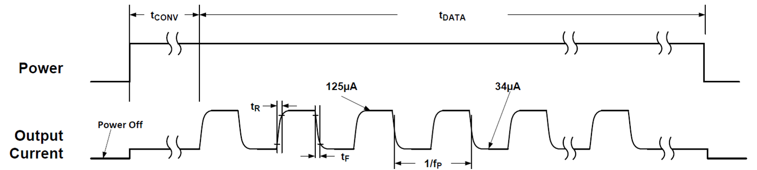
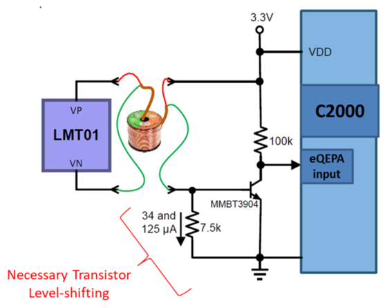
I need to do some temperature measurements in a high noise environment where an NTC just wont do. And it needs to be small, cheap and automotive qualified...because somebody out there hates me, personally. I was looking at the LMT01 which would fit my requirements but I am not sure how to properly capture the data with my C2000. The LMT01 puts out pulses at 88kHz. You switch on the supply and after 54 ms it starts to put out pulses at 88 kHz for up to 50 ms. The number of pulses indicates the temperature.

In an MSP430 I would place a comparator on the output, enable the internal filter with a 5µs filter duration in the comparator to prevent noise from being counted as a pulse and then wire the comparator output as clock into a timer. Reset the timer at start, check the timer count register (equivalent to the number of "clock" pulses that came in), do the conversion, done.

How do I do that in the C2000? Running interrupts every 10µs for up to 34 ms is not an option and I need to distinguish between real pulses (>5 µs) and noise pulses (ballpark 50-100ns). I assume wiring the comparator output into the CLB through the X-Bar would be an option but I don't have CLB experience or the right tools set up.

BR and Thanks

Peter

  • Hi Peter,

    I'm going to share a couple previous solution ideas we came up with using the C2000's eQEP module to interface with the LMT01. I'll mention these haven't been actually tested with HW and SW.

    Solution 1: Two C2000 Pin LMT01-Q1 Power Cycle Method –
     
    Details: LMT01 sensor is powered on using a C2000 GPIO every time a temperature reading is to be taken and powered off once the data transmission is complete. Pulses are counted using C2000 eQEP module in Up-Count mode, eQEPA as the input signal. The eQEP module’s Unit Timer can be used to latch the number of pulses counted into a separate register after the LMT01’s temperature conversion and transmission time (104ms MAX), then the pulse count to temperature conversion calculation can be made. The eQEP pulse counter (QPOSCNT) and Unit Timer (QUPRD) should be reset before each start of conversion.


    Pros:
    •    Simple from a C2000 software perspective with lower CPU utilization/intervention needed

    Cons:
    •    Uses two GPIOs
    •    Have to handle the toggling of the GPIO for temp sensor power

    Solution 2: One C2000 Pin Sequential Read Method -
     
    Details: Similar configuration to solution 1 but remove  need of GPIO for powering up/down the LMT01 and utilize sequential reads from the sensor instead. Temp sensor reads will continuously be transmitted from the LMT01 device. The eQEP module’s watchdog can be used to synchronize the start/end of transmission. Configure eQEP watchdog to timeout after pulses are not witnessed for a certain period of time, in which a timeout will occur and the eQEP pulses counted can be stored/used. The eQEP watchdog will be serviced/reset when pulses are witnessed on its input, so the watchdog timer should be configured to timeout at a period shorter than the minimum LMT01 conversion time, but longer than the longest output pulse period, i.e. 40 ms may be a good timeout so the WD is not always timing out and causing an interrupt.


    Pros:
    •    Only uses one C2000 pin
    •    No need to the manage toggling of a GPIO

    Cons:
    •    More complicated from a software perspective and with (likely) higher CPU utilization/intervention compared to solution 1
    •    Watchdog timeout interrupts will occur every ~104ms and need to be serviced
     
    Best,
    Kevin
  • Thank you for the reply. I actually came up with my own method in the meantime and want to share it because it might be useful to somebody else down the line.

    I saw the option to use the EQEP as a counter in the examples and considered it but. as I said, I have a high noise environment and am worried about getting false positives. I also do have more sensors than EQEP pins (left in the design). So I decided to wire it through the comparator and use a comparator output as EQEP input (which also provides me with the level shift to get a clear signal from the low output voltage).

    So my setup is that several sensors are supplied from Vcc through a pnp transistor switched with a GPIO. Each sensor goes to a different comparator. An X-Bar output is wired into my free EQEP input. I use the Xbar as a multiplexer for the comparators and the comparators as digital filters. Operation is like in your first solution.