This thread has been locked.

If you have a related question, please click the "Ask a related question" button in the top right corner. The newly created question will be automatically linked to this question.

TMS570LS1227: How to connect TMS570LS1227 to XDS110

Part Number: TMS570LS1227
Other Parts Discussed in Thread: HALCOGEN

Hi,

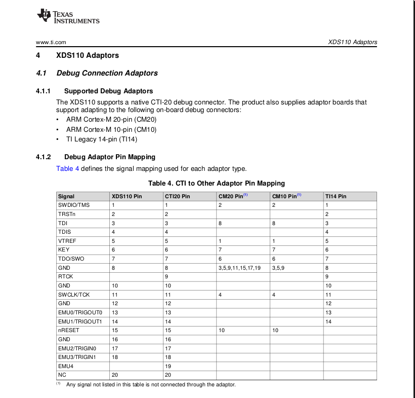
I am having problems with the XDS110 connecting to the LS1227.   Can anybody clarify which XDS110 connections are required as a minimum to be able to download and debug software?  Can anybody confirm / deny if the RTCK signal is required?   According to the XDS110 documentation it doesn't even exist but on the LS1224 EVM with an integrated XDS110 it is connected:

Kind Regards,

  • Hello,

    RTCK means ”Return Test Clock”. It can be used to synchronize the JTAG signals to internal clocks. This allows to reach higher JTAG clock frequencies.

    If your emulator doesn't have RTCK, it is fine.

  • Hi,

    yes, thank you, I know what RTCK is and what it does.  That was not my question.

    > If your emulator doesn't have RTCK, it is fine.

    So, does the TI XDS110 have an RTCK signal or not?

    Kind Regards,

  • From the table in your post (table 4 in sprui94.pdf), XDS110 doesn't have RTCK signal.

  • Hi,

    yes, that's what I wrote already, but in the integrated xds110 schematics of the 1224 EVM it has an RTCK signal.

    Anyway, I found the problem myself in the mean time.   Texas Instruments is shipping faulty adapters with the XDS110.   On the 10 way adapter there is no reset signal.    Although I believe the Cortex R4 doesn't need that TI processors seem to require it.   Also found a thread in this forum from about 4 months ago where somebody had the same problem, so fault was known to TI.   If you solder in R3 on the adapter it works.

    So I would like to take the opportunity to thank TI for the great trouble free software tools (ccs/eclipse) and debug probes they are providing and the great variety of debug connections the design engineer can choose from: (Sorry, can't provide the link because your forum software replaces it with some form of a huge picture)      While you're at it, why don't you reinvent the wheel another few times and create even a few more?   If I could not spend time with getting debuggers and debug connections working I really would not know what to do all day long.

    Kind Regards,

  • I noticed this post and your response , I wanted to add some more guidance based on the discussion we had with emulation experts


    The XDS110, in fact, does not support RTCK nor adaptive clocking. The emulation team confirmed that this pin is really idle – i.e., there is no provision for its functionality in the XDS110 firmware.


    This particular series of Launchpads were an earlier design of the XDS110 and the our team made a decision to make this connection there, perhaps hoping there would be a need for it in the future. This was never used.


    The emulator team do not fully control the design of the Launchpads, but accommodate for some variants. Basically the firmware detects these variants by sampling pins PK4 through PK7 on the TM4C129 device.


    On your other comment:

    Texas Instruments is shipping faulty adapters with the XDS110.   On the 10 way adapter there is no reset signal.   Although I believe the Cortex R4 doesn't need that TI processors seem to require it.   Also found a thread in this forum from about 4 months ago where somebody had the same problem, so fault was known to TI.   If you solder in R3 on the adapter it works.


    I believe you have this incorrect . The ARM 10-pin standard provides a nRESET signal on pin 10, which is connected to pin 15 of the cTI 20 pin connector (check this table) – on the adaptor supplied with the XDS110, this is connected via the resistor R2.

    What you did was short the TRST (which is required by the 5-wire JTAG standard required by our DSPs and C2000 MCUs) to the nRESET (which is a system reset) on the 10-pin adapter. R2 and R3 shouldn’t be fitted at the same time. Hercules devices work well without the TRST signal.


    Also, the ARM Cortex M connectors never provided room to support 5-wire JTAG standard, which includes the signals (TDI, TDO, TCK, TMS, TRST). Reference here

  • Hi Mukul,

    thank you for clarifying the RTCK signal.   Also thanks for the link to the TI debug connector chaos, this was the link I could not include using this forum software.

    May be true what you are saying wrt the adapter but I found a thread here where somebody had exactly the same problem (could have been a 1224) and he solved it too by providing the TRST signal.   Without R3 the XDS110 does not communicate with the 1227.   With R3 it works.   So in this case maybe the XDS110 is not asserting the nRESET but the TRST instead.   Anyway, doesn't really matter it's working for me and I may take R2 out; cannot spent more time on this, lost too much already thanks to misleading signal / peripheral naming in docs and Halcogen (which we hopefully will eliminate soon).

    I will change the debug connector to a 20 way; the 10way looked like a good idea at the time due to space constraints on the board.

    Regards,