This thread has been locked.

If you have a related question, please click the "Ask a related question" button in the top right corner. The newly created question will be automatically linked to this question.

MSP430I2021: About the clock while the fail-safe function is running

Genius 5340 points
Part Number: MSP430I2021

Hi experts,

I would like to know about the fail-safe feature of MSP430I20xx.

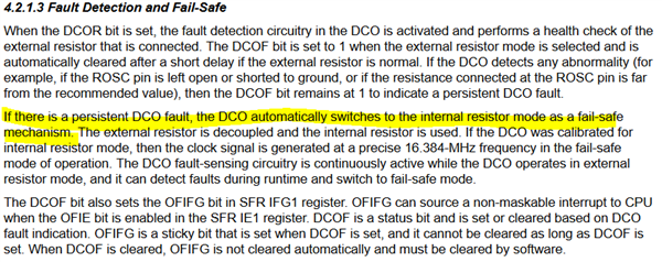
As far as I can tell from "4.2.1.3 Fault Detection and Fail-Safe" in the user's guide, when using the external resistor mode, the DCO fault (For example, the resistor is not connected or is shorted to ground, or the resistance is far from the recommended value) is detected, the DCO automatically switches to the internal resistance mode.

Q:What is the clock used to "switch modes" and "change register contents"?

I think the CPU will not function unless some kind of clock is supplied in order to operate the circuit. Since the system that generates the main clock is abnormal due to a ROSC error, I would like to ask you to check what the system clock is that switches to the internal mode.

ROSC error -> system clock stopped -> what clock is it running on?

Best regards,
O.H

  • Hi experts,

    Sorry for rush. Could you tell us about the status of the investigation?

    My customer is looking for an answer and would appreciate it if you could let me know the status.

    Best regards,
    O.H

  • Hi O.H,

    According to that section of the user's guide, if the DCO detects a problem, it switches to the internal resistance mode.   It wouldn't make sense for the system to detect an error and then simply stop running, so I assume the fail-safe checking is performed while operating on the internal resistance mode.  Then, if no fault detected, it switches to external resistance mode.

  • Hi Dennis Lahman,

    Thank you for your reply.

    It wouldn't make sense for the system to detect an error and then simply stop running, so I assume the fail-safe checking is performed while operating on the internal resistance mode.  Then, if no fault detected, it switches to external resistance mode.

    In the user's guide "4.2.4.3 Use Case 3: DCO Operation With External Resistor - Fault at Startup", it is stated that the DCO fault detection delay period sets DCOF and OFIFG when a fault is detected, but does this mean that the device is actually operating in internal resistance mode?

    Also, if the DCO is already operating in external resistor mode, does the fault detection circuitry operate in internal resistor mode?
    In the user's guide "F4.2.4.4 Use Case 4: DCO Operation With External Resistor - Fault During Run Time", in step 15 I think you are operating in external resistor mode.

    After checking the user's guide again, my view is as follows.

    When a DCO failure occurs, the clock that was running before the occurrence is detected sets DCOF and OFIFG and the clock is stopped. After that, when the fail-safe function is executed, the mode switching does not require the system clock because it is switched hard. Also, after this, the above registers are not changed, so no system clock is needed either.

    Sorry. I understand that there is a discrepancy between the above and the original question, since the original question asked which clocks are used for mode switching and register switching. If the above idea seems wrong, I would appreciate it if you could let me know.

    Best regards,
    O.H

  • Hi O.H,

    Ok - In order to better understand the purpose of the question, why is the customer asking to know the specifics of the fault switching?  Is there a concern about switch-over time?  CPU stall time? Does this make sense what I am asking?

  • Hi Dennis Lahman,

    Thank you for your reply.

    Currently, a customer is experiencing a phenomenon where UART communication stops at high temperatures (40°C). The phenomenon of abnormal communication seems to be an overrun. Due to the high frequency of communication, the rate of occurrence of communication abnormality dropped when we changed the processing load of the CPU so that it could perform reception processing at the right time.

    We are concerned that this problem may have occurred because the DCO mode switching occurs at high temperatures and the CPU stops during the switching period.

    If it is difficult for you to share information about the behavior of DCO mode switching, it would be helpful if you could tell us if DCO mode switching has any impact on this problem.

    Also, have there been any cases in the past of communication errors caused by DCOs in MSP430I2xx series clock systems at high temperatures?

    By the way, has the following "Online tools: Baud Rate Calculator" been discontinued? (SLAA734A:3 Common UART Communication Issues)
    I apologize for my lack of understanding. I would like to calculate the error rate based on the frequency deviation of the DCO at high temperature, but the formula in the user's guide is difficult to understand, so a tool would be helpful.

    Best regards,
    O.H

  • Ok. It's a shame this was not communicated first.  To my knowledge I'm not aware, but let me ask around.

    What baud rate are they using?

    When the customer says communications stops:

    1. Do they mean it misses a few bytes, but keeps working or it completely stops working?

    2. If it is stopping, can software reset and restart communication or does the device need a full reset?

    3. If it is stopping, is the UART receiving or transmitting data, or both when this happens?

    4. Does this happen on more than one device?

    5. Does the CPU switch back and forth from a low power mode to active mode when data is received?  In other words, is the CPU in a lower mode until a byte is received, then CPU wakes and handles the incoming data?  If so, which lower power mode? LPM0, LPM1, LPM2, LPM3?

    Regarding the baud rate tool, yes.  TI is no longer supporting the wikis.

    The software team did post this, however.  It's a simple on-line calculator that determines the USCI or EUSCI parameters based on your clock source and desired baud rate.

    http://software-dl.ti.com/msp430/msp430_public_sw/mcu/msp430/MSP430BaudRateConverter/index.html

  • O.H.,

    What value and tolerance resistor is the customer using?    Do they perform the recommended calibration process?

    See if they can output either the MCLK or SMCLK on one of the GPIO pins and monitor it as the temperature approaches 40C.  They

  • Hi Dennis Lahman,

    Thank you for your reply. And Thank you very much for providing the "simple on-line calculator".

    I reconfirmed their situation.

    When the CPU processing load was changed to be able to process incoming data at the right time, the problem was no longer reproduced, except for one time.

    However, they would like to know where the cause of a single failure is so that they can avoid sudden mass failures in the future. Therefore, they would like to understand how the DCO mode switching works. They are not sure if this is directly related to this problem, so if this information is not available, they would just like to know about similar cases in the past.

    What baud rate are they using?

    When the customer says communications stops:

    1. Do they mean it misses a few bytes, but keeps working or it completely stops working?

    2. If it is stopping, can software reset and restart communication or does the device need a full reset?

    3. If it is stopping, is the UART receiving or transmitting data, or both when this happens?

    4. Does this happen on more than one device?

    5. Does the CPU switch back and forth from a low power mode to active mode when data is received?  In other words, is the CPU in a lower mode until a byte is received, then CPU wakes and handles the incoming data?  If so, which lower power mode? LPM0, LPM1, LPM2, LPM3?

    This is a duplicate, but since they can no longer reproduce it, I will answer in the previous state.

    The baud rate is 38400.

    1. When they checked using the line monitor, no data was observed, so it seems that communication had stopped

    2. It was necessary to reset the device.

    3. This is an overrun on reception.

    4. The number of units is unknown, but it is all of the prototype boards.

    5. We did not check the causal relationship with the power consumption mode. We will check for the future.

    What value and tolerance resistor is the customer using?    Do they perform the recommended calibration process?

    See if they can output either the MCLK or SMCLK on one of the GPIO pins and monitor it as the temperature approaches 40C.

    Since the output pins of MCLK and SMCLK could not be used due to the hardware configuration, the oscillation characteristics of the DCO were pseudo-checked by toggling the leftover GPIO pins. Sorry, I made a mistake in my description. As for the temperature, it was 70°C instead of 40°C. The resistance value was checked in the range of tens [kΩ] to more than 20 [kΩ]. When the resistance value was low, the oscillation characteristics had a relatively large margin, but when it was high, there was no margin.

    Since the problem itself has been solved once, it would be helpful if they had a little information about the DCO mode switching mechanism or similar cases in the past, but if not, they gave up.

    Best regards,
    O.H

**Attention** This is a public forum