This thread has been locked.

If you have a related question, please click the "Ask a related question" button in the top right corner. The newly created question will be automatically linked to this question.

MSP430FR5969: I2C sample code for the MSP430FR5969 microcontroller to communicate with the TMP117 temperature sensor

Part Number: MSP430FR5969
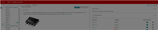
Other Parts Discussed in Thread: TMP117, , SYSCONFIG, TMP007, BOOSTXL-BASSENSORS, MSP430F5528

Hi,

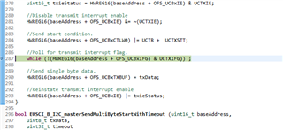
Is there any I2C sample code for the MSP430FR5969 microcontroller to communicate with the TMP117 temperature sensor. I have already downloaded the tmp117.c, tmp117.h, mcu.c, mcu.h, and main.c from SysConfig tool but the mcu.c file would have to modify for MSP430FR5969 I2C peripheral. Any sample code would be very helpful, thanks. 

  • Hello,

    MSP430 isn't supported by the SysConfig tool, according to the devices listed on the SysConfig page. I would recommend starting with the following resources:

  • Hi James, 

    Thank you for the reply. 

    But the mcu.c file can be modified for MSP430 MCUs. Would it be possible to use the functions of the msp430fr59xx_eusci_i2c_standard_master.c file (as you mentioned above ) and modify the mcu.c file to get the data from the sensor. 

    8508.mcu.c
    /*
     *  Include Generic Header Files Here
     */
    #include <stdint.h>
    #include <stdbool.h>
    
    #include "mcu.h"
    
    /*
     *  Include MCU Specific Header Files Here
     */
    
    /********* MCU SPECIFIC I2C CODE STARTS HERE**********/
    
    void mcu_i2cInit(uint8_t busId)
    {
        /* Add MCU specific init necessary for I2C to be used */
    }
    
    int8_t mcu_i2cTransfer( uint8_t busId, uint8_t i2cAddr,
                            uint8_t *dataToWrite, uint8_t writeLength,
                            uint8_t *dataToRead,  uint8_t readLength)
    {
        /*
         *  Add MCU specific I2C read/write code here.
         */
    
        /*
         *  Add MCU specific return code for error handling
         */
    
        return (0);
    }
    /********* MCU SPECIFIC I2C CODE ENDS HERE**********/
    
    
    /********* MCU SPECIFIC DELAY CODE ENDS HERE************/
    void mcu_msWait(unsigned long msWait)
    {
        /*
         *  Add MCU specific wait loop for msWait. The unit is in milli-seconds
         */
    }
    /********* MCU SPECIFIC DELAY CODE ENDS HERE************/
    6763.mcu.h
    8764.main.c
    /*
     *  ======== main.c ========
     *  Simple example that uses the Sensors APIs
     */
     
    #include "TMP117.h"
    
    #include "mcu.h"  /* for mcu_msWait() */
    #define sleep(sec) mcu_msWait(1000 * (sec))
    
    extern const TMP117_Handle TMP117_0;
    
    int32_t tmp1170Temp;
    int32_t tmp1170TempAsIntCelsius;
    int32_t tmp1170TempAsMilliCelsius;
    float tmp1170TempAsFloatCelsius;
    
    /*
     *  ======== main ========
     */
    int main(void)
    {
        /* init sensors with values specified in ti_sensors_config.c */
        TMP117_config(TMP117_0);
    
        for (;;) {
            /* delay 1 sec */
            /* in continuous modes (CC), polling rate should
            not exceed sensor conversion rate */
            sleep(1);
    
            /* Read TMP117_0 temp */
            tmp1170Temp = TMP117_read(TMP117_0);
            tmp1170TempAsIntCelsius = TMP117_toIntCelsius(tmp1170Temp);
            tmp1170TempAsMilliCelsius = TMP117_toMilliCelsius(tmp1170Temp);
            tmp1170TempAsFloatCelsius = TMP117_toFloatCelsius(tmp1170Temp);
    
        }
    }
    5758.TMP117.c
    /*
     *  ======== TMP117.c ========
     *  TMP117 APIs for initialization and use of the TMP117 peripheral
     *
     *  DO NOT EDIT - This file is generated by the SysConfig tool for
     *  the TI Sensors in this application.
     */
    
    #include <stddef.h>
    #include <stdint.h>
    
    #include "TMP117.h"
    #include "mcu.h"
    
    #define TMP117_0_CONFIG_VALUE (TMP117_CONFIG_CONV_MODE_CC | \
                                   TMP117_CONFIG_CONV_CYCLE_1s | \
                                   TMP117_CONFIG_AVG_MODE_8AVG | \
                                   TMP117_CONFIG_TnA_ALERT | \
                                   TMP117_CONFIG_ALERT_POL_LOW | \
                                   TMP117_CONFIG_CRDY_EN_ALERT | \
                                   TMP117_CONFIG_SOFT_RESET_DISABLE)
    #define TMP117_0_THIGH_VALUE 0x6000U /* Alert High Limit is 192 Celsius */
    #define TMP117_0_TLOW_VALUE 0x8000U /* Alert Low Limit is -256 Celsius */
    #define TMP117_0_EEPROM_VALUE TMP117_EEPROM_EUN_DISABLE
    #define TMP117_0_EEPROM1_VALUE 0x0000U
    #define TMP117_0_EEPROM2_VALUE 0x0000U
    #define TMP117_0_EEPROM3_VALUE 0x0000U
    #define TMP117_0_OFFSET_TEMP_VALUE 0x0000U
    
    static TMP117_State TMP117_0_state = {
        .config = TMP117_0_CONFIG_VALUE,
    
        .tHigh  = TMP117_0_THIGH_VALUE,
        .tLow   = TMP117_0_TLOW_VALUE,
    
        .offsetTemp = TMP117_0_OFFSET_TEMP_VALUE,
    
        .eEPROM1 = TMP117_0_EEPROM1_VALUE,
        .eEPROM2 = TMP117_0_EEPROM2_VALUE,
        .eEPROM3 = TMP117_0_EEPROM3_VALUE,
        /* Sensor's I2C bus ID and address */
        .busId   = 0,
        .devAddr = 0x48U,
    
        /* nonvolatile save mode for TMP117_0 registers */
        .nvmCommit = 0, /* don't save registers to EEPROM */
    
        /* preserve factory EEPROM NIST traceability data */
        .preserveNIST = 1, /* 1 => never overwrite NIST data, 0 => allow overwrite */
    
        /* one-shot delay time (ms) */
        .osWait  = 125    
    };
    const TMP117_Handle TMP117_0 = &TMP117_0_state;
    
    
    #define MSB(u16) (((u16) & 0xFF00U) >> 8)
    #define LSB(u16) ((u16) & 0xFFU)
    
    /*
     *  ======== lock ========
     *  Lock out writes to EEPROM NVM
     */
    static inline void lock(TMP117_Handle sensor)
    {
        uint8_t txBuf[3];
    
        /* EEPROM_Unlock Register Write to Lock the NVM */
        txBuf[0] = TMP117_EEPROM;
        txBuf[1] = MSB(TMP117_EEPROM_EUN_DISABLE);
        txBuf[2] = LSB(TMP117_EEPROM_EUN_DISABLE);
        mcu_i2cTransfer(sensor->busId, sensor->devAddr, txBuf, 3, NULL, 0);
    }
    
    /*
     *  ======== unlock ========
     *  Unlock EEPROM NVM so sensor register writes will be saved
     */
    static inline void unlock(TMP117_Handle sensor)
    {
        uint8_t txBuf[3];
    
        /* EEPROM_Unlock Register Write to Unlock the NVM */
        txBuf[0] = TMP117_EEPROM;
        txBuf[1] = MSB(TMP117_EEPROM_EUN_ENABLE);
        txBuf[2] = LSB(TMP117_EEPROM_EUN_ENABLE);
        mcu_i2cTransfer(sensor->busId, sensor->devAddr, txBuf, 3, NULL, 0);
    }
    
    /*
     *  ======== pollBusy ========
     *  Poll EEPROM_Busy flag until it's 0 (not busy)
     */
    static void pollBusy(TMP117_Handle sensor)
    {
        uint8_t txBuf[1];
        uint8_t rxBuf[2];
    
        /* verify that EEPROM isn't busy */
        do {
            /* EEPROM_Unlock Register Read to get the Busy flag */
            txBuf[0] = TMP117_EEPROM;
            mcu_i2cTransfer(sensor->busId, sensor->devAddr, txBuf, 1, rxBuf, 2);
    
            /* EEPROM_Busy is in the MSB of the unlock register */
        } while (rxBuf[0] & MSB(TMP117_EEPROM_EEPROM_BUSY_ENABLE));
    }
    
    /*
     *  ======== writeDelay ========
     *  If necessary, wait for a register write to be saved to EEPROM
     */
    static void writeDelay(TMP117_Handle sensor)
    {
        if (!sensor->nvmCommit) {
            return; /* nothing to do if we're not saving to EEPROM */
        }
    
        /* Wait delay 7 milliseconds for EEPROM to not be busy */
        mcu_msWait(7);
    
        /* wait for sensor to not be busy */
        pollBusy(sensor);
    }
    
    /*
     *  ======== writeReg ========
     */
    static void writeReg(TMP117_Handle sensor, int regAddr, uint16_t value)
    {
        uint8_t txBuf[3];
    
        txBuf[0] = regAddr;
        txBuf[1] = MSB(value);
        txBuf[2] = LSB(value);
        mcu_i2cTransfer(sensor->busId, sensor->devAddr, txBuf, 3, NULL, 0);
        writeDelay(sensor);
    }
    
    /*
     *  ======== reset ========
     *  Reset the sensor and wait for it to be ready
     */
    static void reset(TMP117_Handle sensor)
    {
        uint8_t txBuf[3];
    
        txBuf[0] = TMP117_CONFIG;
        txBuf[1] = MSB(TMP117_CONFIG_SOFT_RESET_ENABLE);
        txBuf[2] = LSB(TMP117_CONFIG_SOFT_RESET_ENABLE);
        mcu_i2cTransfer(sensor->busId, sensor->devAddr, txBuf, 3, NULL, 0);
        mcu_msWait(2);
    }
    
    /*
     *  ======== TMP117_config ========
     *  Configure device with current settings
     *
     *  Note: after a sensor reset, the EEPROM is locked and remains locked for
     *  approximatly 1.5 ms and all register writes are ignored.
     */
    void TMP117_config(TMP117_Handle sensor)
    {
        mcu_i2cInit(sensor->busId);
    
        /* Ensure sensor is not processing a reset */
        pollBusy(sensor);
    
        if (sensor->nvmCommit) {
            /* Unlock EEPROM if we're saving registers */
            unlock(sensor);
        }
    
        /* High Limit Register Write */
        writeReg(sensor, TMP117_THIGH, sensor->tHigh);
    
        /* Low Limit Register Write */
        writeReg(sensor, TMP117_TLOW, sensor->tLow);
    
        /* Temperature Offset Register Write */
        writeReg(sensor, TMP117_OFFSET_TEMP, sensor->offsetTemp);
        
        if (!sensor->preserveNIST) {
            /* EEPROMx Registers Write */
            writeReg(sensor, TMP117_EEPROM1, sensor->eEPROM1);
            writeReg(sensor, TMP117_EEPROM2, sensor->eEPROM2);
            writeReg(sensor, TMP117_EEPROM3, sensor->eEPROM3);
        }
    
        /* Configuration Register Write */
        /* Ensure SOFT_RESET isn't set - otherwise CONFIG setting won't work */
        writeReg(sensor, TMP117_CONFIG, sensor->config & (~TMP117_CONFIG_SOFT_RESET_ENABLE));
    
        /* lock EEPROM to ensure it's no longer writeable */
        if (sensor->config & TMP117_CONFIG_SOFT_RESET_ENABLE) {
            reset(sensor); /* reset also locks EEPROM */
        }
        else {
            lock(sensor);
        }
    }
    
    /*
     *  ======== TMP117_read ========
     *  Read raw temperature value
     */
    int32_t TMP117_read(TMP117_Handle sensor)
    {
        uint8_t txBuf[3];
        uint8_t rxBuf[2];
        int32_t tmp;
    
        /* If needed, trigger one shot measurement */
        if (sensor->config & TMP117_CONFIG_CONV_MODE_SD) {
            /* Reset one-shot enable */
            txBuf[0] = TMP117_CONFIG;
            txBuf[1] = MSB(sensor->config | TMP117_OS_ENABLE);
            txBuf[2] = LSB(sensor->config);
            mcu_i2cTransfer(sensor->busId, sensor->devAddr, txBuf, 3, NULL, 0);
    
            /* Wait for conversion to complete */
            mcu_msWait(sensor->osWait);
        }
    
        /* Temperature Register Read */
        txBuf[0] = TMP117_TEMP;
        mcu_i2cTransfer(sensor->busId, sensor->devAddr, txBuf, 1, rxBuf, 2);
    
        /* Sign extend and combine */
        tmp = (((int32_t)(int8_t)rxBuf[0]) << 8) | rxBuf[1];
    
        return (tmp);
    }
    
    /*
     *  ======== TMP117_toIntCelsius ========
     *  Convert raw temperature register value to degrees Celsius rounded to the
     *  nearest integer
     */
    int32_t TMP117_toIntCelsius(int32_t x)
    {
        /* Optional: Add bias to round before the final truncation */
        x += (x >= 0) ? (1 << 6) : -(1 << 6);
    
        /* Convert Q7 value to whole number */
        x /= 1 << 7; /* use division so small negative values round to 0 */
    
        return x;
    }
    
    /*
     *  ======== TMP117_toMilliCelsius ========
     *  Convert raw temperature register value to milli-degrees Celsius
     */
    int32_t TMP117_toMilliCelsius(int32_t x)
    {
        /* Scale to milli-degrees, convert Q7 value to a whole number */
        return ((1000 * x) >> 7);
    }
    
    /*
     *  ======== TMP117_toFloatCelsius ========
     *  Convert raw temperature register value to degrees Celsius
     */
    float TMP117_toFloatCelsius(int32_t x)
    {
        /* Convert Q7 value to a float */
        return ((float)x * 0.0078125f);
    }


    6116.TMP117.h

  • I would start with the resources that I mentioned rather than trying to modify the mcu.c file. Where did you find these files?

  • Thanks for sharing the links. When the source isn't provided, it's hard to know where to find files that are mentioned. Our temperature sensor team is responsible for those SysConfig projects, so I am not familiar with them. I did download several files such as 'mcu.c', 'main.c', 'tmp117.c', etc., and I think your earlier comments about adding code to those files from the I2C code examples make sense.

    I have gone through the resources that you have suggested but I'm most interested to use the MSP430FR5969 MCU in my project, not the BOOSTXL-SENSORS BoosterPack.

    Keep in mind that BoosterPacks do not contain a MCU and are simple low-cost sensor modules that can plug into your LaunchPad. A LaunchPad will feature a MCU such as the MSP430FR5969, and a BoosterPack allows you to quickly and easily connect the MCU to other sensors without needing jumper wires or a bread board. The BOOSTXL-SENSORS BoosterPack should include some code examples that will be a valuable reference for your development, even if the TMP device is slightly different. I found the newer BOOSTXL-BASSENSORS BoosterPack which features the TMP117 sensor, but the code examples are all RTOS-based and I didn't see any for MSP430 MCUs. Thus, I would use the examples from the other BoosterPack as a reference instead. For example, check out the 'i2c_driver.c' file. This seems to use DriverLib which may save you some work.

  • Here is the mcu.c I use to test Sysconfig code on my MSP430F5528 based EVMs. I don't think it will be compatible with an FR device, but you can use it as a starting point with 430 driverlib.

    /*
     *  Include Generic Header Files Here
     */
    #include <stdint.h>
    #include <stdbool.h>
    
    #include "mcu.h"
    #include "driverlib.h"
    
    unsigned char transmitLength = 0;
    unsigned char transmitCount = 0;
    unsigned char *transmitBuffer;
    unsigned char receiveCount = 0;
    unsigned char *receiveBuffer;
    
    /********* MCU SPECIFIC I2C CODE STARTS HERE**********/
    
    void mcu_i2cInit(uint8_t busId) {
    	//Stop WDT
    	WDT_A_hold(WDT_A_BASE);
    	//Set the internal pull-up resistors
    	//Ports 4.2 and 4.1 are SCL/SDA, respectively
    	GPIO_setAsInputPinWithPullUpResistor(
    	GPIO_PORT_P4,
    	GPIO_PIN1 + GPIO_PIN2);
    
    	//Assign I2C pins to USCI_B1
    	GPIO_setAsPeripheralModuleFunctionOutputPin(
    	GPIO_PORT_P4,
    	GPIO_PIN1 + GPIO_PIN2);
    
    	//Initialize Master
    	USCI_B_I2C_initMasterParam param = { 0 };
    	param.selectClockSource = USCI_B_I2C_CLOCKSOURCE_SMCLK;
    	param.i2cClk = UCS_getSMCLK();
    	param.dataRate = USCI_B_I2C_SET_DATA_RATE_100KBPS;
    	USCI_B_I2C_initMaster(USCI_B1_BASE, &param);
    
    	//Set Transmit mode
    	USCI_B_I2C_setMode(USCI_B1_BASE, USCI_B_I2C_TRANSMIT_MODE);
    
    	//Enable I2C Module to start operations
    	USCI_B_I2C_enable(USCI_B1_BASE);
    }
    
    int8_t mcu_i2cTransfer(uint8_t busId, uint8_t i2cAddr, uint8_t *dataToWrite, uint8_t writeLength, uint8_t *dataToRead, uint8_t readLength) {
    	USCI_B_I2C_setSlaveAddress(USCI_B1_BASE, i2cAddr);
    	if (writeLength) {
    		transmitBuffer = dataToWrite;
    		transmitLength = writeLength;
    		USCI_B_I2C_setMode(USCI_B1_BASE, USCI_B_I2C_TRANSMIT_MODE);
    		USCI_B_I2C_clearInterrupt(USCI_B1_BASE, USCI_B_I2C_TRANSMIT_INTERRUPT);
    		USCI_B_I2C_enableInterrupt(USCI_B1_BASE, USCI_B_I2C_TRANSMIT_INTERRUPT);
    		//Delay between each transaction
    //    __delay_cycles(50);
    		//Load TX byte counter
    		transmitCount = 1;
    		//Initiate start and send first character
    		USCI_B_I2C_masterSendMultiByteStart(USCI_B1_BASE, transmitBuffer[0]);
    		//Enter low power mode 0 with interrupts enabled.
    		__bis_SR_register(LPM0_bits + GIE);
    		//__no_operation();
    	}
    	if (readLength) {
    		//Delay until transmission completes
    //    while(USCI_B_I2C_isBusBusy(USCI_B1_BASE))
    //    {
    //        ;
    //    }
    		USCI_B_I2C_setMode(USCI_B1_BASE, USCI_B_I2C_RECEIVE_MODE);
    		//Enable master Receive interrupt
    		USCI_B_I2C_enableInterrupt(USCI_B1_BASE, USCI_B_I2C_RECEIVE_INTERRUPT);
    		USCI_B_I2C_clearInterrupt(USCI_B1_BASE, USCI_B_I2C_RECEIVE_INTERRUPT);
    		receiveCount = readLength;
    		receiveBuffer = dataToRead;
    		if (receiveCount == 1) {
    //            USCI_B_I2C_disableInterrupt(USCI_B1_BASE,USCI_B_I2C_RECEIVE_INTERRUPT);
    //            USCI_B_I2C_clearInterrupt(USCI_B1_BASE,USCI_B_I2C_RECEIVE_INTERRUPT);
    //            USCI_B_I2C_masterReceiveSingleStart(USCI_B1_BASE);
    
    //            dataToRead[0] = USCI_B_I2C_masterReceiveMultiByteNext(USCI_B1_BASE);
    			//Set USCI in Receive mode
    			HWREG8(USCI_B1_BASE + OFS_UCBxCTL1) &= ~UCTR;
    
    			//Send start condition.
    			HWREG8(USCI_B1_BASE + OFS_UCBxCTL1) |= UCTXSTT;
    
    			//Poll for Start bit to complete
    			while (HWREG8(USCI_B1_BASE + OFS_UCBxCTL1) & UCTXSTT) {
    				;
    			}
    
    			//Send stop condition.
    			HWREG8(USCI_B1_BASE + OFS_UCBxCTL1) |= UCTXSTP;
    			__bis_SR_register(LPM0_bits + GIE);
    		} else {
    			USCI_B_I2C_masterReceiveMultiByteStart(USCI_B1_BASE);
    			//Enter low power mode 0 with interrupts enabled.
    			__bis_SR_register(LPM0_bits + GIE);
    		}
    	}
    	return (0);
    }
    /********* MCU SPECIFIC I2C CODE ENDS HERE**********/
    
    /********* MCU SPECIFIC DELAY CODE ENDS HERE************/
    void mcu_msWait(unsigned long msWait) {
    	__delay_cycles(50);
    }
    /********* MCU SPECIFIC DELAY CODE ENDS HERE************/
    
    #if defined(__TI_COMPILER_VERSION__) || defined(__IAR_SYSTEMS_ICC__)
    #pragma vector = USCI_B1_VECTOR;
    __interrupt
    #elif defined(__GNUC__)
    __attribute__((interrupt(USCI_B1_VECTOR)))
    #endif
    void USCI_B1_ISR(void) {
    	switch (__even_in_range(UCB1IV, 12)) {
    	case USCI_I2C_UCTXIFG: {
    		//Check TX byte counter
    		if (transmitCount < transmitLength) {
    			//Initiate send of character from Master to Slave
    			USCI_B_I2C_masterSendMultiByteNext(USCI_B1_BASE, transmitBuffer[transmitCount]);
    
    			//Increment TX byte counter
    			transmitCount++;
    		} else {
    			//Initiate stop only
    			USCI_B_I2C_masterSendMultiByteStop(USCI_B1_BASE);
    
    			//Clear master interrupt status
    			USCI_B_I2C_clearInterrupt(USCI_B1_BASE,
    			USCI_B_I2C_TRANSMIT_INTERRUPT);
    
    			//Exit LPM0 on interrupt return
    			__bic_SR_register_on_exit(LPM0_bits);
    		}
    		break;
    	}
    	case USCI_I2C_UCRXIFG: {
    		//Decrement RX byte counter
    		receiveCount--;
    		if (receiveCount) {
    			if (receiveCount == 1) {
    				//Initiate end of reception -> Receive byte with NAK
    				*receiveBuffer++ = USCI_B_I2C_masterReceiveMultiByteNext(USCI_B1_BASE);
    				USCI_B_I2C_clearInterrupt(USCI_B1_BASE, USCI_B_I2C_RECEIVE_INTERRUPT);
    				__bic_SR_register_on_exit(LPM0_bits);
    			} else {
    				//Keep receiving one byte at a time
    				*receiveBuffer++ = USCI_B_I2C_masterReceiveMultiByteNext(USCI_B1_BASE);
    			}
    		} else {
    			//Receive last byte
    			*receiveBuffer = USCI_B_I2C_masterReceiveMultiByteNext(USCI_B1_BASE);
    			USCI_B_I2C_disableInterrupt(USCI_B1_BASE, USCI_B_I2C_RECEIVE_INTERRUPT);
    			USCI_B_I2C_clearInterrupt(USCI_B1_BASE, USCI_B_I2C_RECEIVE_INTERRUPT);
    			__bic_SR_register_on_exit(LPM0_bits);
    		}
    		break;
    	}
    	}
    }
    

  • Thank you James and Ren for your help. 

    I'm trying to analyze the waveform of the SCL and SDA bus via an oscilloscope. I'm getting a very strange waveform when I run the msp430fr59xx_eusci_i2c_standard_master.c. I've attached the image below. I'm using LaunchPad with MSP430FR5969 and connected to the TMP117 (with slave address of 0*048). I used 10K pullup resistors. 

    When I run the code, the build, load and initialize go successfully but stops at various places and give the message such as MSP430-Debug Call Stack. How can I resolve this issue. 

    and the same debug issue at the following function as well:

    Stack size:

    However, if I run the eusci_b_i2c_ex2_masterRxSingle.c from the resource explorer, I've got the following waveform without having any debugging issues, which look identical. 

    Many thanks

  • I would encourage you to go through the I2C Academy and Solutions to Common eUSCI and USCI Serial Communication Issues on MSP430 MCUs that I linked earlier.

    I used 10K pullup resistors

    That's a little high. I'd recommend lowering that to 4.7k or less, especially if you're communicating faster than 100kHz and using jumper wires that add capacitance to the I2C lines.

    I'm getting a very strange waveform when I run the msp430fr59xx_eusci_i2c_standard_master.c.

    Thanks for describing which examples you're using. This example is register-level code and the I2C clock speed is 100kHz.

    When I run the code, the build, load and initialize go successfully but stops at various places and give the message such as MSP430-Debug Call Stack. How can I resolve this issue. 

    Keep in mind that the device goes into low power mode at certain times. It's not really an issue.

    However, if I run the eusci_b_i2c_ex2_masterRxSingle.c from the resource explorer, I've got the following waveform without having any debugging issues, which look identical. 

    This example is library-level code and the I2C clock speed is 400kHz.

  • Hi James,

    Thank you for the reply. I have followed the I2C master example "msp430fr243x_eusci_i2c_standard_master.c" which is described in the MSP430 I2C Academy article, and modified the msp430fr59xx_eusci_i2c_standard_master.c for TMP117 accordingly. They have also set the SMCLK to 100 kHz but they get the right waveform. I don't know why I'm getting the wrong waveform. What do I need to do to get the right waveform?

    Many thanks

  • Hi James, 

    I changed the value of delay function from 1600000 to 2000 milliseconds and now I'm getting the following waveform:

    Below is the modified code:

    //******************************************************************************
    //   MSP430FR59xx Demo - eUSCI_B0, I2C Master multiple byte TX/RX
    //
    //   Description: I2C master communicates to I2C slave sending and receiving
    //   3 different messages of different length. I2C master will enter LPM0 mode
    //   while waiting for the messages to be sent/receiving using I2C interrupt.
    //   ACLK = NA, MCLK = SMCLK = DCO 16MHz.
    //
    //                                     /|\ /|\
    //                   MSP430FR5969      4.7k |
    //                 -----------------    |  4.7k
    //            /|\ |             P1.7|---+---|-- I2C Clock (UCB0SCL)
    //             |  |                 |       |
    //             ---|RST          P1.6|-------+-- I2C Data (UCB0SDA)
    //                |                 |
    //                |                 |
    //                |                 |
    //                |                 |
    //                |                 |
    //                |                 |
    //
    //   Nima Eskandari
    //   Texas Instruments Inc.
    //   April 2017
    //   Built with CCS V7.0
    //******************************************************************************
    
    #include <msp430.h> 
    #include <stdint.h>
    #include <stdbool.h>
    
    //******************************************************************************
    // Example Commands ************************************************************
    //******************************************************************************
    
    #define SLAVE_ADDR  0x48
    #define CONVERSION_READY  0x10
    
    #define TMP117_TEMP_REG  0x00
    #define TMP117_CONFIG_REG  0x01
    
    /* CMD_TYPE_X_SLAVE are example commands the master sends to the slave.
     * The slave will send example SlaveTypeX buffers in response.
     *
     * CMD_TYPE_X_MASTER are example commands the master sends to the slave.
     * The slave will initialize itself to receive MasterTypeX example buffers.
     * */
    
    #define CMD_TYPE_0_SLAVE      0
    #define CMD_TYPE_1_SLAVE      1
    #define CMD_TYPE_2_SLAVE      2
    
    #define CMD_TYPE_0_MASTER      3
    #define CMD_TYPE_1_MASTER      4
    #define CMD_TYPE_2_MASTER      5
    
    #define TYPE_0_LENGTH   1
    #define TYPE_1_LENGTH   2
    #define TYPE_2_LENGTH   6
    
    #define MAX_BUFFER_SIZE     20
    
    /* MasterTypeX are example buffers initialized in the master, they will be
     * sent by the master to the slave.
     * SlaveTypeX are example buffers initialized in the slave, they will be
     * sent by the slave to the master.
     * */
    
    uint8_t MasterType2 [TYPE_2_LENGTH] = {'F', '4', '1', '9', '2', 'B'};
    //uint8_t MasterType1 [TYPE_1_LENGTH] = { 8, 9};
    uint8_t MasterType1 [TYPE_1_LENGTH] = {0x02, 0x20};
    
    uint8_t MasterType0 [TYPE_0_LENGTH] = {11};
    
    
    uint8_t SlaveType2 [TYPE_2_LENGTH] = {0};
    uint8_t SlaveType1 [TYPE_1_LENGTH] = {0};
    uint8_t SlaveType0 [TYPE_0_LENGTH] = {0};
    
    //******************************************************************************
    // General I2C State Machine ***************************************************
    //******************************************************************************
    
    typedef enum I2C_ModeEnum{
        IDLE_MODE,
        NACK_MODE,
        TX_REG_ADDRESS_MODE,
        RX_REG_ADDRESS_MODE,
        TX_DATA_MODE,
        RX_DATA_MODE,
        SWITCH_TO_RX_MODE,
        SWITHC_TO_TX_MODE,
        TIMEOUT_MODE
    } I2C_Mode;
    
    
    /* Used to track the state of the software state machine*/
    I2C_Mode MasterMode = IDLE_MODE;
    
    /* The Register Address/Command to use*/
    uint8_t TransmitRegAddr = 0;
    
    /* ReceiveBuffer: Buffer used to receive data in the ISR
     * RXByteCtr: Number of bytes left to receive
     * ReceiveIndex: The index of the next byte to be received in ReceiveBuffer
     * TransmitBuffer: Buffer used to transmit data in the ISR
     * TXByteCtr: Number of bytes left to transfer
     * TransmitIndex: The index of the next byte to be transmitted in TransmitBuffer
     * */
    uint8_t ReceiveBuffer[MAX_BUFFER_SIZE] = {0};
    uint8_t RXByteCtr = 0;
    uint8_t ReceiveIndex = 0;
    uint8_t TransmitBuffer[MAX_BUFFER_SIZE] = {0};
    uint8_t TXByteCtr = 0;
    uint8_t TransmitIndex = 0;


    /* I2C Write and Read Functions */
    
    /* For slave device with dev_addr, writes the data specified in *reg_data
     *
     * dev_addr: The slave device address.
     *           Example: SLAVE_ADDR
     * reg_addr: The register or command to send to the slave.
     *           Example: CMD_TYPE_0_MASTER
     * *reg_data: The buffer to write
     *           Example: MasterType0
     * count: The length of *reg_data
     *           Example: TYPE_0_LENGTH
     *  */
    I2C_Mode I2C_Master_WriteReg(uint8_t dev_addr, uint8_t reg_addr, uint8_t *reg_data, uint8_t count);
    
    /* For slave device with dev_addr, read the data specified in slaves reg_addr.
     * The received data is available in ReceiveBuffer
     *
     * dev_addr: The slave device address.
     *           Example: SLAVE_ADDR
     * reg_addr: The register or command to send to the slave.
     *           Example: CMD_TYPE_0_SLAVE
     * count: The length of data to read
     *           Example: TYPE_0_LENGTH
     *  */
    I2C_Mode I2C_Master_ReadReg(uint8_t dev_addr, uint8_t reg_addr, uint8_t count);
    void CopyArray(uint8_t *source, uint8_t *dest, uint8_t count);
    
    
    I2C_Mode I2C_Master_ReadReg(uint8_t dev_addr, uint8_t reg_addr, uint8_t count)
    {
        /* Initialize state machine */
        MasterMode = TX_REG_ADDRESS_MODE;
        TransmitRegAddr = reg_addr;
        RXByteCtr = count;
        TXByteCtr = 0;
        ReceiveIndex = 0;
        TransmitIndex = 0;
    
        /* Initialize slave address and interrupts */
        UCB0I2CSA = dev_addr;
        UCB0IFG &= ~(UCTXIFG + UCRXIFG);       // Clear any pending interrupts
        UCB0IE &= ~UCRXIE;                       // Disable RX interrupt
        UCB0IE |= UCTXIE;                        // Enable TX interrupt
    
        UCB0CTLW0 |= UCTR + UCTXSTT;             // I2C TX, start condition
        __bis_SR_register(LPM0_bits + GIE);              // Enter LPM0 w/ interrupts
    
        return MasterMode;
    
    }
    
    
    I2C_Mode I2C_Master_WriteReg(uint8_t dev_addr, uint8_t reg_addr, uint8_t *reg_data, uint8_t count)
    {
        /* Initialize state machine */
        MasterMode = TX_REG_ADDRESS_MODE;
        TransmitRegAddr = reg_addr;
    
        //Copy register data to TransmitBuffer
        CopyArray(reg_data, TransmitBuffer, count);
    
        TXByteCtr = count;
        RXByteCtr = 0;
        ReceiveIndex = 0;
        TransmitIndex = 0;
    
        /* Initialize slave address and interrupts */
        UCB0I2CSA = dev_addr;
        UCB0IFG &= ~(UCTXIFG + UCRXIFG);       // Clear any pending interrupts
        UCB0IE &= ~UCRXIE;                       // Disable RX interrupt
        UCB0IE |= UCTXIE;                        // Enable TX interrupt
    
        UCB0CTLW0 |= UCTR + UCTXSTT;             // I2C TX, start condition
        __bis_SR_register(LPM0_bits + GIE);              // Enter LPM0 w/ interrupts
    
        return MasterMode;
    }
    
    void CopyArray(uint8_t *source, uint8_t *dest, uint8_t count)
    {
        uint8_t copyIndex = 0;
        for (copyIndex = 0; copyIndex < count; copyIndex++)
        {
            dest[copyIndex] = source[copyIndex];
        }
    }
    
    
    //******************************************************************************
    // Device Initialization *******************************************************
    //******************************************************************************
    
    
    void initGPIO()
    {
        // Configure GPIO
        P1OUT &= ~BIT0;                           // Clear P1.0 output latch
        P1DIR |= BIT0;                            // For LED
        P1SEL1 |= BIT6 | BIT7;                    // I2C pins
        // Disable the GPIO power-on default high-impedance mode to activate
        // previously configured port settings
        PM5CTL0 &= ~LOCKLPM5;
    }
    
    void initClockTo16MHz()
    {
        // Configure one FRAM waitstate as required by the device datasheet for MCLK
        // operation beyond 8MHz _before_ configuring the clock system.
        FRCTL0 = FRCTLPW | NWAITS_1;
    
        // Clock System Setup
        CSCTL0_H = CSKEY >> 8;                    // Unlock CS registers
        CSCTL1 = DCORSEL | DCOFSEL_4;             // Set DCO to 16MHz
        CSCTL2 = SELA__VLOCLK | SELS__DCOCLK | SELM__DCOCLK;
        CSCTL3 = DIVA__1 | DIVS__1 | DIVM__1;     // Set all dividers
    
        CSCTL0_H = 0;                             // Lock CS registerss
    }
    
    void initI2C()
    {
        UCB0CTLW0 = UCSWRST;                      // Enable SW reset
        UCB0CTLW0 |= UCMODE_3 | UCMST | UCSSEL__SMCLK | UCSYNC; // I2C master mode, SMCLK
        UCB0BRW = 160;                            // fSCL = SMCLK/160 = ~100kHz
        UCB0I2CSA = SLAVE_ADDR;                   // Slave Address
        UCB0CTLW0 &= ~UCSWRST;                    // Clear SW reset, resume operation
        UCB0IE |= UCNACKIE;
    }
    
    
    //******************************************************************************
    // Main ************************************************************************
    // Send and receive three messages containing the example commands *************
    //******************************************************************************
    
    int main(void) {
        WDTCTL = WDTPW | WDTHOLD;	// Stop watchdog timer
        initClockTo16MHz();
        initGPIO();
        initI2C();
    
        //I2C_Master_WriteReg(SLAVE_ADDR, CMD_TYPE_0_MASTER, MasterType0, TYPE_0_LENGTH);
        I2C_Master_WriteReg(SLAVE_ADDR, 0x01, MasterType1, TYPE_1_LENGTH);
        while(1)
        {
            _delay_cycles(2000);
    
            I2C_Master_ReadReg(SLAVE_ADDR, 0x00, TYPE_1_LENGTH);
            CopyArray(ReceiveBuffer, SlaveType1, TYPE_1_LENGTH);
    
            if(ReceiveBuffer[1] & CONVERSION_READY)
            {
                I2C_Master_ReadReg(SLAVE_ADDR, 0x00, TYPE_1_LENGTH);
                CopyArray(ReceiveBuffer, SlaveType1, TYPE_1_LENGTH);
    
                _no_operation();
            }
       }
    
        //I2C_Master_WriteReg(SLAVE_ADDR, CMD_TYPE_2_MASTER, MasterType2, TYPE_2_LENGTH);
    
        ///I2C_Master_ReadReg(SLAVE_ADDR, CMD_TYPE_0_SLAVE, TYPE_0_LENGTH);
        //CopyArray(ReceiveBuffer, SlaveType0, TYPE_0_LENGTH);
    
        //I2C_Master_ReadReg(SLAVE_ADDR, 0x00, TYPE_1_LENGTH);
        //CopyArray(ReceiveBuffer, SlaveType1, TYPE_1_LENGTH);
    
       //I2C_Master_ReadReg(SLAVE_ADDR, CMD_TYPE_2_SLAVE, TYPE_2_LENGTH);
       // CopyArray(ReceiveBuffer, SlaveType2, TYPE_2_LENGTH);
    
       // __bis_SR_register(LPM0_bits + GIE);
    	//return 0;
    }
    
    
    //******************************************************************************
    // I2C Interrupt ***************************************************************
    //******************************************************************************
    
    #if defined(__TI_COMPILER_VERSION__) || defined(__IAR_SYSTEMS_ICC__)
    #pragma vector = USCI_B0_VECTOR
    __interrupt void USCI_B0_ISR(void)
    #elif defined(__GNUC__)
    void __attribute__ ((interrupt(USCI_B0_VECTOR))) USCI_B0_ISR (void)
    #else
    #error Compiler not supported!
    #endif
    {
      //Must read from UCB0RXBUF
      uint8_t rx_val = 0;
      switch(__even_in_range(UCB0IV, USCI_I2C_UCBIT9IFG))
      {
        case USCI_NONE:          break;         // Vector 0: No interrupts
        case USCI_I2C_UCALIFG:   break;         // Vector 2: ALIFG
        case USCI_I2C_UCNACKIFG:                // Vector 4: NACKIFG
          break;
        case USCI_I2C_UCSTTIFG:  break;         // Vector 6: STTIFG
        case USCI_I2C_UCSTPIFG:  break;         // Vector 8: STPIFG
        case USCI_I2C_UCRXIFG3:  break;         // Vector 10: RXIFG3
        case USCI_I2C_UCTXIFG3:  break;         // Vector 12: TXIFG3
        case USCI_I2C_UCRXIFG2:  break;         // Vector 14: RXIFG2
        case USCI_I2C_UCTXIFG2:  break;         // Vector 16: TXIFG2
        case USCI_I2C_UCRXIFG1:  break;         // Vector 18: RXIFG1
        case USCI_I2C_UCTXIFG1:  break;         // Vector 20: TXIFG1
        case USCI_I2C_UCRXIFG0:                 // Vector 22: RXIFG0
            rx_val = UCB0RXBUF;
            if (RXByteCtr)
            {
              ReceiveBuffer[ReceiveIndex++] = rx_val;
              RXByteCtr--;
            }
    
            if (RXByteCtr == 1)
            {
              UCB0CTLW0 |= UCTXSTP;
            }
            else if (RXByteCtr == 0)
            {
              UCB0IE &= ~UCRXIE;
              MasterMode = IDLE_MODE;
              __bic_SR_register_on_exit(CPUOFF);      // Exit LPM0
            }
            break;
        case USCI_I2C_UCTXIFG0:                 // Vector 24: TXIFG0
            switch (MasterMode)
            {
              case TX_REG_ADDRESS_MODE:
                  UCB0TXBUF = TransmitRegAddr;
                  if (RXByteCtr)
                      MasterMode = SWITCH_TO_RX_MODE;   // Need to start receiving now
                  else
                      MasterMode = TX_DATA_MODE;        // Continue to transmision with the data in Transmit Buffer
                  break;
    
              case SWITCH_TO_RX_MODE:
                  UCB0IE |= UCRXIE;              // Enable RX interrupt
                  UCB0IE &= ~UCTXIE;             // Disable TX interrupt
                  UCB0CTLW0 &= ~UCTR;            // Switch to receiver
                  MasterMode = RX_DATA_MODE;    // State state is to receive data
                  UCB0CTLW0 |= UCTXSTT;          // Send repeated start
                  if (RXByteCtr == 1)
                  {
                      //Must send stop since this is the N-1 byte
                      while((UCB0CTLW0 & UCTXSTT));
                      UCB0CTLW0 |= UCTXSTP;      // Send stop condition
                  }
                  break;
    
              case TX_DATA_MODE:
                  if (TXByteCtr)
                  {
                      UCB0TXBUF = TransmitBuffer[TransmitIndex++];
                      TXByteCtr--;
                  }
                  else
                  {
                      //Done with transmission
                      UCB0CTLW0 |= UCTXSTP;     // Send stop condition
                      MasterMode = IDLE_MODE;
                      UCB0IE &= ~UCTXIE;                       // disable TX interrupt
                      __bic_SR_register_on_exit(CPUOFF);      // Exit LPM0
                  }
                  break;
    
              default:
                  __no_operation();
                  break;
            }
            break;
        default: break;
      }
    }

  • Hi Ren, 

    I have tried to modify your code for the MSP430FR5969 MCU. However, I can't get any data from the sensor. I am trying to read the TM117 temperature sensor which has the following specifications.

    TMP117 sensor address = 0x48                                                                                                                                                                                  Temperature register =  0x00
    Configuration register =  0x01                                                                                                                                                                                      TMP117 RESOLUTION 0.0078125f 

    I don't know how to properly modified the read function in your code to get data from the sensor. Could you please help to modify the write and read functions with the reference to TM117 sensor specifications.

    This is the modified code.

    #include <msp430.h>
    #include "driverlib.h"
    #include <stdint.h>
    #include <stdbool.h>
    
    #include "mcu.h"
    
    unsigned char transmitLength = 0;
    unsigned char transmitCount = 0;
    unsigned char *transmitBuffer;
    unsigned char receiveCount = 0;
    unsigned char *receiveBuffer;
    
    
    #define SLAVE_ADDR  0x48        // sensor address 
    
    #define TMP117_TEMP_REG  0x00   //temperature register
    #define TMP117_CONFIG_REG  0x01  //Configuration registry
    
    #define TMP117_RESOLUTION 0.0078125f // sensor resolution 
    
    void mcu_i2cInit(uint8_t busId) {
    
        //Stop WDT
        WDT_A_hold(WDT_A_BASE);
    
        //Set the internal pull-up resistors
        //Ports 4.2 and 4.1 are SCL/SDA, respectively
        //GPIO_setAsInputPinWithPullUpResistor(GPIO_PORT_P4,
        //GPIO_PIN1 + GPIO_PIN2);
    
        //Assign I2C pins to USCI_B1
        //GPIO_setAsPeripheralModuleFunctionOutputPin(
        //GPIO_PORT_P4,
        //GPIO_PIN1 + GPIO_PIN2);
    
        GPIO_setAsPeripheralModuleFunctionInputPin(
                GPIO_PORT_P1,
                GPIO_PIN6 + GPIO_PIN7,
                GPIO_SECONDARY_MODULE_FUNCTION
            );
        PMM_unlockLPM5();
    
            //Initialize Master
            EUSCI_B_I2C_initMasterParam param = {0};
            param.selectClockSource = EUSCI_B_I2C_CLOCKSOURCE_SMCLK;
            param.i2cClk = CS_getSMCLK();
            param.dataRate = EUSCI_B_I2C_SET_DATA_RATE_100KBPS;
            EUSCI_B_I2C_initMaster(EUSCI_B0_BASE, &param);
    
            //Set Transmit mode
            EUSCI_B_I2C_setMode(EUSCI_B0_BASE, EUSCI_B_I2C_TRANSMIT_MODE);
    
            //Enable I2C Module to start operations
            EUSCI_B_I2C_enable(EUSCI_B0_BASE);
        }
    
        int8_t mcu_i2cTransfer(uint8_t busId, uint8_t i2cAddr, uint8_t *dataToWrite, uint8_t writeLength, uint8_t *dataToRead, uint8_t readLength) {
            EUSCI_B_I2C_setSlaveAddress(EUSCI_B0_BASE, i2cAddr);
            if (writeLength) {
                transmitBuffer = dataToWrite;
                transmitLength = writeLength;
                EUSCI_B_I2C_setMode(EUSCI_B0_BASE, EUSCI_B_I2C_TRANSMIT_MODE);
                EUSCI_B_I2C_clearInterrupt(EUSCI_B0_BASE, EUSCI_B_I2C_TRANSMIT_INTERRUPT0);
                EUSCI_B_I2C_enableInterrupt(EUSCI_B0_BASE, EUSCI_B_I2C_TRANSMIT_INTERRUPT0);
                //Delay between each transaction
            __delay_cycles(50);
                //Load TX byte counter
                transmitCount = 1;
                //Initiate start and send first character
                EUSCI_B_I2C_masterSendMultiByteStart(EUSCI_B0_BASE, transmitBuffer[0]);
                //Enter low power mode 0 with interrupts enabled.
                __bis_SR_register(LPM0_bits + GIE);
                //__no_operation();
            }
            if (readLength) {
                //Delay until transmission completes
        //    while(USCI_B_I2C_isBusBusy(EUSCI_B0_BASE))
        //    {
        //        ;
        //    }
                EUSCI_B_I2C_setMode(EUSCI_B0_BASE, EUSCI_B_I2C_RECEIVE_MODE);
                //Enable master Receive interrupt
                EUSCI_B_I2C_enableInterrupt(EUSCI_B0_BASE, EUSCI_B_I2C_RECEIVE_INTERRUPT0);
                EUSCI_B_I2C_clearInterrupt(EUSCI_B0_BASE, EUSCI_B_I2C_RECEIVE_INTERRUPT0);
                receiveCount = readLength;
                receiveBuffer = dataToRead;
    
                if (receiveCount == 1) {
    
                   EUSCI_B_I2C_disableInterrupt(EUSCI_B0_BASE, EUSCI_B_I2C_RECEIVE_INTERRUPT0);
                   EUSCI_B_I2C_clearInterrupt(EUSCI_B0_BASE, EUSCI_B_I2C_RECEIVE_INTERRUPT0);
                   EUSCI_B_I2C_masterReceiveStart(EUSCI_B0_BASE);


                    //dataToRead[0] = EUSCI_B_I2C_masterReceiveMultiByteNext(EUSCI_B0_BASE);
                    //Set USCI in Receive mode
                    HWREG16(EUSCI_B0_BASE + OFS_UCBxCTLW0) &= ~UCTR;
    
                    //Send start condition.
                    HWREG16(EUSCI_B0_BASE + OFS_UCBxCTLW0) |= UCTXSTT;
    
                    //Poll for Start bit to complete
                    while (HWREG16(EUSCI_B0_BASE + OFS_UCBxCTLW0) & UCTXSTT) {
                        ;
                    }
    
                    //Send stop condition.
                    HWREG16(EUSCI_B0_BASE + OFS_UCBxCTLW0) |= UCTXSTP;
                    __bis_SR_register(LPM0_bits + GIE);
                }
                else {
                    EUSCI_B_I2C_masterReceiveStart(EUSCI_B0_BASE);
                    //Enter low power mode 0 with interrupts enabled.
                    __bis_SR_register(LPM0_bits + GIE);
                }
            }
            return (0);
        }
    
    
        /********* MCU SPECIFIC I2C CODE ENDS HERE**********/
    
        /********* MCU SPECIFIC DELAY CODE ENDS HERE************/
        void mcu_msWait(unsigned long msWait) {
            __delay_cycles(50);
        }
        /********* MCU SPECIFIC DELAY CODE ENDS HERE************/


        #if defined(__TI_COMPILER_VERSION__) || defined(__IAR_SYSTEMS_ICC__)
        #pragma vector = USCI_B0_VECTOR;
        __interrupt
        #elif defined(__GNUC__)
        __attribute__((interrupt(USCI_B0_VECTOR)))
        #endif
        void USCI_B1_ISR(void) {
            switch (__even_in_range(UCB0IV, 12)) {
            case USCI_I2C_UCTXIFG0: {
                //Check TX byte counter
                if (transmitCount < transmitLength) {
                    //Initiate send of character from Master to Slave
                    EUSCI_B_I2C_masterSendMultiByteNext(EUSCI_B0_BASE, transmitBuffer[transmitCount]);
    
                    //Increment TX byte counter
                    transmitCount++;
                } else {
                    //Initiate stop only
                    EUSCI_B_I2C_masterSendMultiByteStop(EUSCI_B0_BASE);
    
                    //Clear master interrupt status
                    EUSCI_B_I2C_clearInterrupt(EUSCI_B0_BASE,
                    EUSCI_B_I2C_TRANSMIT_INTERRUPT0);
    
                    //Exit LPM0 on interrupt return
                    __bic_SR_register_on_exit(LPM0_bits);
                }
                break;
            }
            case USCI_I2C_UCRXIFG0: {
                //Decrement RX byte counter
                receiveCount--;
                if (receiveCount) {
                    if (receiveCount == 1) {
                        //Initiate end of reception -> Receive byte with NAK
                        *receiveBuffer++ = EUSCI_B_I2C_masterReceiveMultiByteNext(EUSCI_B0_BASE);
                        EUSCI_B_I2C_clearInterrupt(EUSCI_B0_BASE, EUSCI_B_I2C_RECEIVE_INTERRUPT0);
                        __bic_SR_register_on_exit(LPM0_bits);
                    } else {
                        //Keep receiving one byte at a time
                        *receiveBuffer++ = EUSCI_B_I2C_masterReceiveMultiByteNext(EUSCI_B0_BASE);
                    }
                } else {
                    //Receive last byte
                    *receiveBuffer = EUSCI_B_I2C_masterReceiveMultiByteNext(EUSCI_B0_BASE);
                    EUSCI_B_I2C_disableInterrupt(EUSCI_B0_BASE, EUSCI_B_I2C_RECEIVE_INTERRUPT0);
                    EUSCI_B_I2C_clearInterrupt(EUSCI_B0_BASE, EUSCI_B_I2C_RECEIVE_INTERRUPT0);
                    __bic_SR_register_on_exit(LPM0_bits);
                }
                break;
            }
            }
        }
    

    Many thanks.

  • I have tried to modify your code for the MSP430FR5969 MCU. However, I can't get any data from the sensor. I am trying to read the TM117 temperature sensor which has the following specifications.

    Are you referring to the write and read timing diagrams provided in the TMP117 datasheet? Section 7.5.3.1.3 Writing and Reading Operation in the datasheet should also be helpful. How do your commands compare to these? Is the TMP117 sending an ACK or a NACK? Where does the communication stop working correctly?

  • Hi James,

    Thank you for the reply.

    I'm trying to use the I2C functions to modify the mcu.c file so that I can use the TM117.h library to read the temperature values. The code REN suggested is a bit different from the msp430fr59xx_eusci_i2c_standard_master.c.

    Are you referring to the write and read timing diagrams provided in the TMP117 datasheet?

    That's right. I'm not sure how to properly modify the write and read commands in the mcu.c file that REN suggested. I used the following read and write functions in the msp430fr59xx_eusci_i2c_standard_master.c to read the TM117 temperature register which works fine. 

    int main(void) {
        WDTCTL = WDTPW | WDTHOLD;	// Stop watchdog timer
        initClockTo16MHz();
        initGPIO();
        initI2C();
    
        //I2C_Master_WriteReg(SLAVE_ADDR, CMD_TYPE_0_MASTER, MasterType0, TYPE_0_LENGTH);
        I2C_Master_WriteReg(SLAVE_ADDR, 0x01, MasterType1, TYPE_1_LENGTH);
        while(1)
        {
    
           _delay_cycles(500000);
           // _delay_cycles(1600);
    
            I2C_Master_ReadReg(SLAVE_ADDR, 0x00, TYPE_1_LENGTH);
            CopyArray(ReceiveBuffer, SlaveType1, TYPE_1_LENGTH);
    
            if(ReceiveBuffer[1] & CONVERSION_READY)
            {
                I2C_Master_ReadReg(SLAVE_ADDR, 0x00, TYPE_1_LENGTH);
                CopyArray(ReceiveBuffer, SlaveType1, TYPE_1_LENGTH);
                _no_operation();
            }
    
       }

    Is the TMP117 sending an ACK or a NACK?

    This is what I get:

    Where does the communication stop working correctly?

    When I suspend the debug, the code stuck in the EUSCI_B_I2C file, as shown below and as a result, it never finishes execution. Just to make it clear there are four files: (1) main.c, (ii) mcu.c, (iii) mcu.h (iv) tmp117.c, and (v) tmp117.h.

    Many thanks

  • That's right. I'm not sure how to properly modify the write and read commands in the mcu.c file that REN suggested. I used the following read and write functions in the msp430fr59xx_eusci_i2c_standard_master.c to read the TM117 temperature register which works fine. 

    You may need to reorganize some of the write and read functions to achieve this. For example, the "read" commands for the TMP117 sensor may still require a write before reading the data.

    When I suspend the debug, the code stuck in the EUSCI_B_I2C file, as shown below and as a result, it never finishes execution.

    Perhaps this is because you're using code that was originally intended for a F5xx device whereas you're using a FR59xx device. You may want to read through the Enhanced Universal Serial Communication Interface section of the Migrating from the MSP430F5xx and MSP430F6xx Family to the MSP430FR58xx/FR59xx/68xx/69xx Family app note. Also, I would check the FR59xx user's guide to learn more about why the TXIFG isn't getting set after disabling the interrupts and sending a start condition.

  • Hi James,

    I hope you're well. I'm trying to print a string on an external terminal (I used PuTTY) using a UART interface. I've modified the msp430fr59xx_euscia0_uart_03.c  to transmit an integer number such as 56. I'm hoping that I can use the UART interface to print the temperature value on the terminal.

    This is the modified code of the msp430fr59xx_euscia0_uart_03.c:

    /* --COPYRIGHT--,BSD_EX
     * Copyright (c) 2012, Texas Instruments Incorporated
     * All rights reserved.
     *
     * Redistribution and use in source and binary forms, with or without
     * modification, are permitted provided that the following conditions
     * are met:
     *
     * *  Redistributions of source code must retain the above copyright
     *    notice, this list of conditions and the following disclaimer.
     *
     * *  Redistributions in binary form must reproduce the above copyright
     *    notice, this list of conditions and the following disclaimer in the
     *    documentation and/or other materials provided with the distribution.
     *
     * *  Neither the name of Texas Instruments Incorporated nor the names of
     *    its contributors may be used to endorse or promote products derived
     *    from this software without specific prior written permission.
     *
     * THIS SOFTWARE IS PROVIDED BY THE COPYRIGHT HOLDERS AND CONTRIBUTORS "AS IS"
     * AND ANY EXPRESS OR IMPLIED WARRANTIES, INCLUDING, BUT NOT LIMITED TO,
     * THE IMPLIED WARRANTIES OF MERCHANTABILITY AND FITNESS FOR A PARTICULAR
     * PURPOSE ARE DISCLAIMED. IN NO EVENT SHALL THE COPYRIGHT OWNER OR
     * CONTRIBUTORS BE LIABLE FOR ANY DIRECT, INDIRECT, INCIDENTAL, SPECIAL,
     * EXEMPLARY, OR CONSEQUENTIAL DAMAGES (INCLUDING, BUT NOT LIMITED TO,
     * PROCUREMENT OF SUBSTITUTE GOODS OR SERVICES; LOSS OF USE, DATA, OR PROFITS;
     * OR BUSINESS INTERRUPTION) HOWEVER CAUSED AND ON ANY THEORY OF LIABILITY,
     * WHETHER IN CONTRACT, STRICT LIABILITY, OR TORT (INCLUDING NEGLIGENCE OR
     * OTHERWISE) ARISING IN ANY WAY OUT OF THE USE OF THIS SOFTWARE,
     * EVEN IF ADVISED OF THE POSSIBILITY OF SUCH DAMAGE.
     *
     *******************************************************************************
     *
     *                       MSP430 CODE EXAMPLE DISCLAIMER
     *
     * MSP430 code examples are self-contained low-level programs that typically
     * demonstrate a single peripheral function or device feature in a highly
     * concise manner. For this the code may rely on the device's power-on default
     * register values and settings such as the clock configuration and care must
     * be taken when combining code from several examples to avoid potential side
     * effects. Also see www.ti.com/grace for a GUI- and www.ti.com/msp430ware
     * for an API functional library-approach to peripheral configuration.
     *
     * --/COPYRIGHT--*/
    //******************************************************************************
    //  MSP430FR59xx Demo - USCI_A0 External Loopback test @ 115200 baud
    //
    //  Description: This demo connects TX to RX of the MSP430 UART
    //  The example code shows proper initialization of registers
    //  and interrupts to receive and transmit data. If data is incorrect P1.0 LED is
    //  turned ON.
    //  ACLK = n/a, MCLK = SMCLK = BRCLK = default DCO = 1MHz
    //
    //
    //                MSP430FR5969
    //             -----------------
    //       RST -|     P2.0/UCA0TXD|----|
    //            |                 |    |
    //           -|                 |    |
    //            |     P2.1/UCA0RXD|----|
    //            |                 |
    //            |             P1.0|---> LED
    //
    //   P. Thanigai
    //   Texas Instruments Inc.
    //   August 2012
    //   Built with CCS V4 and IAR Embedded Workbench Version: 5.5
    //******************************************************************************
    #include <msp430.h>
    #include <string.h>
    #include <ctype.h>
    #include <stdio.h>
    #include <stdlib.h>
    
    //volatile unsigned char RXData = 0;
    //volatile unsigned char TXData = 1;
    
       char RXbuffer[32];
       const unsigned char maxRXbytes = sizeof(RXbuffer);
       unsigned char RXbytes = 0;
    
       const char message[] = "ok\n";
       const unsigned char messageLength = sizeof(message);
       unsigned char TXbytes = 0;
    
       const char firstquestion[] = "Hello World\n ";
       unsigned int i=0;
    
       int temp = 56;
       char stringTemp[80];
       unsigned int len;
    
    int main(void)
    {
      WDTCTL = WDTPW | WDTHOLD;                 // Stop watchdog
    
      // Configure GPIO
      P1OUT &= ~BIT0;                           // Clear P1.0 output latch
      P1DIR |= BIT0;                            // For LED on P1.0
      P2SEL1 |= BIT0 | BIT1;                    // USCI_A0 UART operation
      P2SEL0 &= ~(BIT0 | BIT1);
    
      // Disable the GPIO power-on default high-impedance mode to activate
      // previously configured port settings
      PM5CTL0 &= ~LOCKLPM5;
    
      // Configure USCI_A0 for UART mode
      UCA0CTLW0 = UCSWRST;                      // Put eUSCI in reset
      UCA0CTL1 |= UCSSEL__SMCLK;                // CLK = SMCLK
      UCA0BR0 = 8;                              // 1000000/115200 = 8.68
      UCA0MCTLW = 0xD600;                       // 1000000/115200 - INT(1000000/115200)=0.68
                                                // UCBRSx value = 0xD6 (See UG)
      UCA0BR1 = 0;
      UCA0CTL1 &= ~UCSWRST;                     // release from reset
      //UCA0IE |= UCRXIE;                         // Enable USCI_A0 RX interrupt


      while (1)
      {
       // while(!(UCA0IFG & UCTXIFG));
        //UCA0TXBUF = TXData;                     // Load data onto buffer
    
       //UCA0TXBUF = message[TXbytes];
    
        // If last byte sent, disable the interrupt
       //if(TXbytes == messageLength)
       // {
           // UCA0IE &= ~UCTXIE;
           // TXbytes = 0;
       // }
    
          //for(i=0; i<strlen(firstquestion); i++)   //loops through first question elements and outputs
          // {
              // while (!(UCA0IFG & UCTXIFG));          //waits for character
               //UCA0TXBUF = firstquestion[i];         //sets character to for element of first question
    
          // }
    
         sprintf(stringTemp, "%d\n", temp);
    
          len = strlen(stringTemp);
    
          for(i=0; i<len; i++){
                while(!(UCA0IFG&UCTXIFG));
                UCA0TXBUF = stringTemp[i];
                }
    
        __bis_SR_register(LPM0_bits | GIE);     // Enter LPM0, interrupts enabled
    
      }
    }
    
    #if defined(__TI_COMPILER_VERSION__) || defined(__IAR_SYSTEMS_ICC__)
    #pragma vector=USCI_A0_VECTOR
    __interrupt void USCI_A0_ISR(void)
    #elif defined(__GNUC__)
    void __attribute__ ((interrupt(USCI_A0_VECTOR))) USCI_A0_ISR (void)
    #else
    #error Compiler not supported!
    #endif
    {
      switch(__even_in_range(UCA0IV,USCI_UART_UCTXCPTIFG))
      {
        case USCI_NONE: break;
        case USCI_UART_UCRXIFG:
          //RXData = UCA0RXBUF;                   // Read buffer
          //if(RXData != TXData)                  // Check value
         // {
           // P1OUT |= BIT0;                      // If incorrect turn on P1.0
             // while(1);                         // Trap CPU
         // }
         // TXData++;                             // increment data byte
         // __bic_SR_register_on_exit(LPM0_bits); // Exit LPM0 on reti
          break;
        case USCI_UART_UCTXIFG: break;
        case USCI_UART_UCSTTIFG: break;
        case USCI_UART_UCTXCPTIFG: break;
      }
    }

    This is what I get:

    This sample code only works for sending a message or an integer number, but it is not working for floating-point numbers.  I used %f instead of %d in the sprintf function and also define float temp = 56.0123 but I get an error. I was wondering how to print a floating number? such as 56.0123. 

    sprintf(stringTemp, "%d\n", temp);

    I also tried to combine both codes. I defined a new function called "int uart()" in the msp430fr59xx_eusci_i2c_standard_master.c, and copy all code from  of msp430fr59xx_euscia0_uart_03.c and pasted in the  "int uart()" function. Then I recalled the "int uart()" function in the main loop of the msp430fr59xx_eusci_i2c_standard_master.c. This is the combined code:

    //******************************************************************************
    //   MSP430FR59xx Demo - eUSCI_B0, I2C Master multiple byte TX/RX
    //
    //   Description: I2C master communicates to I2C slave sending and receiving
    //   3 different messages of different length. I2C master will enter LPM0 mode
    //   while waiting for the messages to be sent/receiving using I2C interrupt.
    //   ACLK = NA, MCLK = SMCLK = DCO 16MHz.
    //
    //                                     /|\ /|\
    //                   MSP430FR5969      4.7k |
    //                 -----------------    |  4.7k
    //            /|\ |             P1.7|---+---|-- I2C Clock (UCB0SCL)
    //             |  |                 |       |
    //             ---|RST          P1.6|-------+-- I2C Data (UCB0SDA)
    //                |                 |
    //                |                 |
    //                |                 |
    //                |                 |
    //                |                 |
    //                |                 |
    //
    //   Nima Eskandari
    //   Texas Instruments Inc.
    //   April 2017
    //   Built with CCS V7.0
    //******************************************************************************
    
    #include <stdio.h>
    #include <msp430.h> 
    #include <stdint.h>
    #include <stdbool.h>
    
    #include <string.h>
    #include <ctype.h>
    #include <stdlib.h>
    
    //******************************************************************************
    // Example Commands ************************************************************
    //******************************************************************************
    
    #define SLAVE_ADDR  0x48
    #define CONVERSION_READY  0x10
    
    #define TMP117_TEMP_REG  0x00
    #define TMP117_CONFIG_REG  0x01
    
    #define TMP117_RESOLUTION 0.0078125f
    
    /* CMD_TYPE_X_SLAVE are example commands the master sends to the slave.
     * The slave will send example SlaveTypeX buffers in response.
     *
     * CMD_TYPE_X_MASTER are example commands the master sends to the slave.
     * The slave will initialize itself to receive MasterTypeX example buffers.
     * */
    
    #define CMD_TYPE_0_SLAVE      0
    #define CMD_TYPE_1_SLAVE      1
    #define CMD_TYPE_2_SLAVE      2
    
    #define CMD_TYPE_0_MASTER      3
    #define CMD_TYPE_1_MASTER      4
    #define CMD_TYPE_2_MASTER      5
    
    #define TYPE_0_LENGTH   1
    #define TYPE_1_LENGTH   2
    #define TYPE_2_LENGTH   6
    
    #define MAX_BUFFER_SIZE     20
    
    /* MasterTypeX are example buffers initialized in the master, they will be
     * sent by the master to the slave.
     * SlaveTypeX are example buffers initialized in the slave, they will be
     * sent by the slave to the master.
     * */
    
    uint8_t MasterType2 [TYPE_2_LENGTH] = {'F', '4', '1', '9', '2', 'B'};
    //uint8_t MasterType1 [TYPE_1_LENGTH] = { 8, 9};
    uint8_t MasterType1 [TYPE_1_LENGTH] = {0x02, 0x20};
    
    uint8_t MasterType0 [TYPE_0_LENGTH] = {11};
    
    
    uint8_t SlaveType2 [TYPE_2_LENGTH] = {0};
    uint8_t SlaveType1 [TYPE_1_LENGTH] = {0};
    uint8_t SlaveType0 [TYPE_0_LENGTH] = {0};
    
       char RXbuffer[32];
       const unsigned char maxRXbytes = sizeof(RXbuffer);
       unsigned char RXbytes = 0;
    
       const char message[] = "ok\n";
       const unsigned char messageLength = sizeof(message);
       unsigned char TXbytes = 0;
    
       const char firstquestion[] = "Hello World\n ";
       unsigned int i=0;
    
       int temp = 56;
       char stringTemp[80];
       unsigned int len;
    
    //******************************************************************************
    // General I2C State Machine ***************************************************
    //******************************************************************************
    
    typedef enum I2C_ModeEnum{
        IDLE_MODE,
        NACK_MODE,
        TX_REG_ADDRESS_MODE,
        RX_REG_ADDRESS_MODE,
        TX_DATA_MODE,
        RX_DATA_MODE,
        SWITCH_TO_RX_MODE,
        SWITHC_TO_TX_MODE,
        TIMEOUT_MODE
    } I2C_Mode;
    
    
    /* Used to track the state of the software state machine*/
    I2C_Mode MasterMode = IDLE_MODE;
    
    /* The Register Address/Command to use*/
    uint8_t TransmitRegAddr = 0;
    
    /* ReceiveBuffer: Buffer used to receive data in the ISR
     * RXByteCtr: Number of bytes left to receive
     * ReceiveIndex: The index of the next byte to be received in ReceiveBuffer
     * TransmitBuffer: Buffer used to transmit data in the ISR
     * TXByteCtr: Number of bytes left to transfer
     * TransmitIndex: The index of the next byte to be transmitted in TransmitBuffer
     * */
    uint8_t ReceiveBuffer[MAX_BUFFER_SIZE] = {0};
    uint8_t RXByteCtr = 0;
    uint8_t ReceiveIndex = 0;
    uint8_t TransmitBuffer[MAX_BUFFER_SIZE] = {0};
    uint8_t TXByteCtr = 0;
    uint8_t TransmitIndex = 0;
    
    
    /* I2C Write and Read Functions */
    
    /* For slave device with dev_addr, writes the data specified in *reg_data
     *
     * dev_addr: The slave device address.
     *           Example: SLAVE_ADDR
     * reg_addr: The register or command to send to the slave.
     *           Example: CMD_TYPE_0_MASTER
     * *reg_data: The buffer to write
     *           Example: MasterType0
     * count: The length of *reg_data
     *           Example: TYPE_0_LENGTH
     *  */
    I2C_Mode I2C_Master_WriteReg(uint8_t dev_addr, uint8_t reg_addr, uint8_t *reg_data, uint8_t count);
    
    /* For slave device with dev_addr, read the data specified in slaves reg_addr.
     * The received data is available in ReceiveBuffer
     *
     * dev_addr: The slave device address.
     *           Example: SLAVE_ADDR
     * reg_addr: The register or command to send to the slave.
     *           Example: CMD_TYPE_0_SLAVE
     * count: The length of data to read
     *           Example: TYPE_0_LENGTH
     *  */
    I2C_Mode I2C_Master_ReadReg(uint8_t dev_addr, uint8_t reg_addr, uint8_t count);
    void CopyArray(uint8_t *source, uint8_t *dest, uint8_t count);
    
    
    I2C_Mode I2C_Master_ReadReg(uint8_t dev_addr, uint8_t reg_addr, uint8_t count)
    {
        /* Initialize state machine */
        MasterMode = TX_REG_ADDRESS_MODE;
        TransmitRegAddr = reg_addr;
        RXByteCtr = count;
        TXByteCtr = 0;
        ReceiveIndex = 0;
        TransmitIndex = 0;
    
        /* Initialize slave address and interrupts */
        UCB0I2CSA = dev_addr;
        UCB0IFG &= ~(UCTXIFG + UCRXIFG);       // Clear any pending interrupts
        UCB0IE &= ~UCRXIE;                       // Disable RX interrupt
        UCB0IE |= UCTXIE;                        // Enable TX interrupt
    
        UCB0CTLW0 |= UCTR + UCTXSTT;             // I2C TX, start condition
        __bis_SR_register(LPM0_bits + GIE);              // Enter LPM0 w/ interrupts
    
        return MasterMode;
    }
    
    I2C_Mode I2C_Master_WriteReg(uint8_t dev_addr, uint8_t reg_addr, uint8_t *reg_data, uint8_t count)
    {
        /* Initialize state machine */
        MasterMode = TX_REG_ADDRESS_MODE;
        TransmitRegAddr = reg_addr;
    
        //Copy register data to TransmitBuffer
        CopyArray(reg_data, TransmitBuffer, count);
    
        TXByteCtr = count;
        RXByteCtr = 0;
        ReceiveIndex = 0;
        TransmitIndex = 0;
    
        /* Initialize slave address and interrupts */
        UCB0I2CSA = dev_addr;
        UCB0IFG &= ~(UCTXIFG + UCRXIFG);       // Clear any pending interrupts
        UCB0IE &= ~UCRXIE;                       // Disable RX interrupt
        UCB0IE |= UCTXIE;                        // Enable TX interrupt
    
        UCB0CTLW0 |= UCTR + UCTXSTT;             // I2C TX, start condition
        __bis_SR_register(LPM0_bits + GIE);              // Enter LPM0 w/ interrupts
    
        return MasterMode;
    }
    
    void CopyArray(uint8_t *source, uint8_t *dest, uint8_t count)
    {
        uint8_t copyIndex = 0;
        for (copyIndex = 0; copyIndex < count; copyIndex++)
        {
            dest[copyIndex] = source[copyIndex];
        }
    }
    
    //******************************************************************************
    // Device Initialization *******************************************************
    //******************************************************************************
    
    void initGPIO()
    {
        // Configure GPIO
        P1OUT &= ~BIT0;                           // Clear P1.0 output latch
        P1DIR |= BIT0;                            // For LED
        P1SEL1 |= BIT6 | BIT7;                    // I2C pins
        // Disable the GPIO power-on default high-impedance mode to activate
        // previously configured port settings
        PM5CTL0 &= ~LOCKLPM5;
    }
    
    void initClockTo16MHz()
    {
        // Configure one FRAM waitstate as required by the device datasheet for MCLK
        // operation beyond 8MHz _before_ configuring the clock system.
        FRCTL0 = FRCTLPW | NWAITS_1;
    
        // Clock System Setup
        CSCTL0_H = CSKEY >> 8;                    // Unlock CS registers
        CSCTL1 = DCORSEL | DCOFSEL_4;             // Set DCO to 16MHz
        CSCTL2 = SELA__VLOCLK | SELS__DCOCLK | SELM__DCOCLK;
        CSCTL3 = DIVA__1 | DIVS__1 | DIVM__1;     // Set all dividers
    
        CSCTL0_H = 0;                             // Lock CS registerss
    }
    
    void initI2C()
    {
        UCB0CTLW0 = UCSWRST;                      // Enable SW reset
        UCB0CTLW0 |= UCMODE_3 | UCMST | UCSSEL__SMCLK | UCSYNC; // I2C master mode, SMCLK
        UCB0BRW = 160;                            // fSCL = SMCLK/160 = ~100kHz
        UCB0I2CSA = SLAVE_ADDR;                   // Slave Address
        UCB0CTLW0 &= ~UCSWRST;                    // Clear SW reset, resume operation
        UCB0IE |= UCNACKIE;
    
    }
    
    //**********************UART****************************************************
    int uart()
    {
     // WDTCTL = WDTPW | WDTHOLD;                 // Stop watchdog
    
      // Configure GPIO
      P1OUT &= ~BIT0;                           // Clear P1.0 output latch
      P1DIR |= BIT0;                            // For LED on P1.0
      P2SEL1 |= BIT0 | BIT1;                    // USCI_A0 UART operation
      P2SEL0 &= ~(BIT0 | BIT1);
    
      // Disable the GPIO power-on default high-impedance mode to activate
      // previously configured port settings
      PM5CTL0 &= ~LOCKLPM5;
    
      // Configure USCI_A0 for UART mode
      UCA0CTLW0 = UCSWRST;                      // Put eUSCI in reset
      UCA0CTL1 |= UCSSEL__SMCLK;                // CLK = SMCLK
      UCA0BR0 = 8;                              // 1000000/115200 = 8.68
      UCA0MCTLW = 0xD600;                       // 1000000/115200 - INT(1000000/115200)=0.68
                                                // UCBRSx value = 0xD6 (See UG)
      UCA0BR1 = 0;
      UCA0CTL1 &= ~UCSWRST;                     // release from reset
      //UCA0IE |= UCRXIE;                         // Enable USCI_A0 RX interrupt
    
      while (1)
      {
    
         sprintf(stringTemp, "%d", temp);
    
          len = strlen(stringTemp);
    
          for(i=0; i<len; i++){
                while(!(UCA0IFG&UCTXIFG));
                UCA0TXBUF = stringTemp[i];
                }
    
       // __bis_SR_register(LPM0_bits | GIE);     // Enter LPM0, interrupts enabled
    
      }
    }
    
    //***************************UART***************************************************
    
    //******************************************************************************
    // Main ************************************************************************
    // Send and receive three messages containing the example commands *************
    //******************************************************************************
    
    int main(void) {
        WDTCTL = WDTPW | WDTHOLD;	// Stop watchdog timer
        initClockTo16MHz();
        initGPIO();
        initI2C();
        uart();
    
        //I2C_Master_WriteReg(SLAVE_ADDR, CMD_TYPE_0_MASTER, MasterType0, TYPE_0_LENGTH);
        I2C_Master_WriteReg(SLAVE_ADDR, 0x01, MasterType1, TYPE_1_LENGTH);
        while(1)
        {
    
           _delay_cycles(500000);
           // _delay_cycles(1600);
    
            I2C_Master_ReadReg(SLAVE_ADDR, 0x00, TYPE_1_LENGTH);
            CopyArray(ReceiveBuffer, SlaveType1, TYPE_1_LENGTH);
    
            if(ReceiveBuffer[1] & CONVERSION_READY)
            {
                I2C_Master_ReadReg(SLAVE_ADDR, 0x00, TYPE_1_LENGTH);
                CopyArray(ReceiveBuffer, SlaveType1, TYPE_1_LENGTH);
                _no_operation();
            }
       }
    
      //  float finalTempC = ReceiveBuffer [1]* TMP117_RESOLUTION;
    
        //return 0;
    }
        //I2C_Master_WriteReg(SLAVE_ADDR, CMD_TYPE_2_MASTER, MasterType2, TYPE_2_LENGTH);
    
        ///I2C_Master_ReadReg(SLAVE_ADDR, CMD_TYPE_0_SLAVE, TYPE_0_LENGTH);
        //CopyArray(ReceiveBuffer, SlaveType0, TYPE_0_LENGTH);
    
        //I2C_Master_ReadReg(SLAVE_ADDR, 0x00, TYPE_1_LENGTH);
        //CopyArray(ReceiveBuffer, SlaveType1, TYPE_1_LENGTH);
    
       //I2C_Master_ReadReg(SLAVE_ADDR, CMD_TYPE_2_SLAVE, TYPE_2_LENGTH);
       // CopyArray(ReceiveBuffer, SlaveType2, TYPE_2_LENGTH);
    
       // __bis_SR_register(LPM0_bits + GIE);
    	//return 0;
    //}
    
    //******************************************************************************
    // I2C Interrupt ***************************************************************
    //******************************************************************************
    
    #if defined(__TI_COMPILER_VERSION__) || defined(__IAR_SYSTEMS_ICC__)
    #pragma vector = USCI_B0_VECTOR
    __interrupt void USCI_B0_ISR(void)
    #elif defined(__GNUC__)
    void __attribute__ ((interrupt(USCI_B0_VECTOR))) USCI_B0_ISR (void)
    #else
    #error Compiler not supported!
    #endif
    {
      //Must read from UCB0RXBUF
      uint8_t rx_val = 0;
      switch(__even_in_range(UCB0IV, USCI_I2C_UCBIT9IFG))
      {
        case USCI_NONE:          break;         // Vector 0: No interrupts
        case USCI_I2C_UCALIFG:   break;         // Vector 2: ALIFG
        case USCI_I2C_UCNACKIFG:                // Vector 4: NACKIFG
          break;
        case USCI_I2C_UCSTTIFG:  break;         // Vector 6: STTIFG
        case USCI_I2C_UCSTPIFG:  break;         // Vector 8: STPIFG
        case USCI_I2C_UCRXIFG3:  break;         // Vector 10: RXIFG3
        case USCI_I2C_UCTXIFG3:  break;         // Vector 12: TXIFG3
        case USCI_I2C_UCRXIFG2:  break;         // Vector 14: RXIFG2
        case USCI_I2C_UCTXIFG2:  break;         // Vector 16: TXIFG2
        case USCI_I2C_UCRXIFG1:  break;         // Vector 18: RXIFG1
        case USCI_I2C_UCTXIFG1:  break;         // Vector 20: TXIFG1
        case USCI_I2C_UCRXIFG0:                 // Vector 22: RXIFG0
            rx_val = UCB0RXBUF;
            if (RXByteCtr)
            {
              ReceiveBuffer[ReceiveIndex++] = rx_val;
              RXByteCtr--;
            }
    
            if (RXByteCtr == 1)
            {
              UCB0CTLW0 |= UCTXSTP;
            }
            else if (RXByteCtr == 0)
            {
              UCB0IE &= ~UCRXIE;
              MasterMode = IDLE_MODE;
              __bic_SR_register_on_exit(CPUOFF);      // Exit LPM0
            }
            break;
        case USCI_I2C_UCTXIFG0:                 // Vector 24: TXIFG0
            switch (MasterMode)
            {
              case TX_REG_ADDRESS_MODE:
                  UCB0TXBUF = TransmitRegAddr;
                  if (RXByteCtr)
                      MasterMode = SWITCH_TO_RX_MODE;   // Need to start receiving now
                  else
                      MasterMode = TX_DATA_MODE;        // Continue to transmision with the data in Transmit Buffer
                  break;
    
              case SWITCH_TO_RX_MODE:
                  UCB0IE |= UCRXIE;              // Enable RX interrupt
                  UCB0IE &= ~UCTXIE;             // Disable TX interrupt
                  UCB0CTLW0 &= ~UCTR;            // Switch to receiver
                  MasterMode = RX_DATA_MODE;    // State state is to receive data
                  UCB0CTLW0 |= UCTXSTT;          // Send repeated start
                  if (RXByteCtr == 1)
                  {
                      //Must send stop since this is the N-1 byte
                      while((UCB0CTLW0 & UCTXSTT));
                      UCB0CTLW0 |= UCTXSTP;      // Send stop condition
                  }
                  break;
    
              case TX_DATA_MODE:
                  if (TXByteCtr)
                  {
                      UCB0TXBUF = TransmitBuffer[TransmitIndex++];
                      TXByteCtr--;
                  }
                  else
                  {
                      //Done with transmission
                      UCB0CTLW0 |= UCTXSTP;     // Send stop condition
                      MasterMode = IDLE_MODE;
                      UCB0IE &= ~UCTXIE;                       // disable TX interrupt
                      __bic_SR_register_on_exit(CPUOFF);      // Exit LPM0
                  }
                  break;
    
              default:
                  __no_operation();
                  break;
            }
            break;
        default: break;
      }
    }
    
    //**********************************uart interrupt****************************
    #if defined(__TI_COMPILER_VERSION__) || defined(__IAR_SYSTEMS_ICC__)
    #pragma vector=USCI_A0_VECTOR
    __interrupt void USCI_A0_ISR(void)
    #elif defined(__GNUC__)
    void __attribute__ ((interrupt(USCI_A0_VECTOR))) USCI_A0_ISR (void)
    #else
    #error Compiler not supported!
    #endif
    {
      switch(__even_in_range(UCA0IV,USCI_UART_UCTXCPTIFG))
      {
        case USCI_NONE: break;
        case USCI_UART_UCRXIFG:
          //RXData = UCA0RXBUF;                   // Read buffer
          //if(RXData != TXData)                  // Check value
         // {
           // P1OUT |= BIT0;                      // If incorrect turn on P1.0
             // while(1);                         // Trap CPU
         // }
         // TXData++;                             // increment data byte
         // __bic_SR_register_on_exit(LPM0_bits); // Exit LPM0 on reti
          break;
        case USCI_UART_UCTXIFG: break;
        case USCI_UART_UCSTTIFG: break;
        case USCI_UART_UCTXCPTIFG: break;
      }
    }
    //**********************************uart interrupt****************************
    

    And this is what I get:

    I would like to know how would I combine the msp430fr59xx_euscia0_uart_03.c and msp430fr59xx_eusci_i2c_standard_master.c, so that I can get data from the sensor through I2C and printed it on the external terminal using printf() function.

    Let me know if you have any questions, many thanks.

  • Hi Irfan,

    I would like to know how would I combine the msp430fr59xx_euscia0_uart_03.c and msp430fr59xx_eusci_i2c_standard_master.c, so that I can get data from the sensor through I2C and printed it on the external terminal using printf() function.

    This is getting outside of the scope of your original question, so I would recommend making a new thread if you continue to have issues with the UART. I would not recommend using floats, but instead scale up integers (e.g. 10.234 > 10234). Combining the examples shouldn't be too hard assuming they are using different modules. I tend not to use print() or sprint() due to increased overhead but have used a lighter version of printf() described here.

**Attention** This is a public forum