This thread has been locked.

If you have a related question, please click the "Ask a related question" button in the top right corner. The newly created question will be automatically linked to this question.

MSP430F1222: ADC10 sampling syncronization

Part Number: MSP430F1222

Dear Forum,

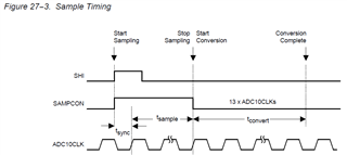
I am a little bit confused by Fig 18-3 in the MSP430F1xx manual showing how the ADC10 takes a sample.

Note, precise samping became important if higher frequency AC signals need to be digitized.

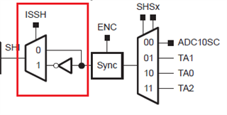
Assuming Tmer_A (TA) module OUT signal does trigg (SHI=OUT1 rise edge) the sampling (periodically).

Assuming both TA module ADC10CLK sourced also from SMCLK. TA counts the rise edge of clock.

TA OUT (and thus SHI) changes its state upon rise edge of SMCLK.

In this setup SHI trigger rising edge totally in phase with ADC10CLK thus 'tsync' ->0 according to Fig 18-3. Can it cause jitter in Sample time interval (no setup/hold time ensured to internal flip-flop) say toggles randomly between 4*Tclk / 5*Tclk?

Or certain internal mechanism allways provides the samling interval defined in the ADC10 control register (by SHTx bits)?

Thanks and regards,

Joseph

  • Hi Joseph,

    I do not think the tsync will be zero at all. The SHI trigger edge will never be in the exactly the same phase with ADC10CLK.

    Best regards,

    Cash Hao

  • Hi Cash Hao,

    does it mean the SHI will always lag behind the common SMCLK (by 10nsec for example)? And therefore samping interval will be (N_SHT + 1 )*tclk ?

    Joseph

  • Try to visualize the ADC as a voltmeter that takes a sample of the voltage from some channel (A0 through A7 or the built-in thermometer), then feeds that sample to a SAR, then the SAR uses a technique called successive approximation register (SAR) to measure the sample and then convert it to a 10-bit number, and then the number is written into the ADC10MEM register where our program can read it.

    You have to configure a range of voltages that will be divided by the SAR into 1,023 equal parts. That’s why it’s called a 10-Bit SAR. The end points of that range are shown as VR- and VR+ by the block diagram for the ADC.

    Taking a sample, measuring it, converting it to a 10 bit number, and then writing it into the register where you can get it, will consume a period of clock cycles (referred to as sample and conversion timing). For that ADC, the period is at least 18 clock cycles long.

    The specification of 200 ksps means that this ADC can go through the sample and conversion period 200,000 times per second. This depends on the clock signal driving the ADC.

    Set the ADC10SC bit to take a sample, and then clear the bit to stop taking a sample. Wait for the sample and conversion period to end, and then read the ADC10MEM register to get the number.

    Read the register descriptions to learn how to use each bitfield to configure the ADC. Many can be used in their default state.

    There is much more to understand, but this information should provide a good starting point for you.

    Good luck in your endeavor.

  • Hi Thomas,

    thank you for the ADC10 detail! I use the ADC10 but I would need a confirmation that sample time is aways the same defined in the ADC10CTLx (pls consider SHI trigger snyc to ACDCLK). When ADC10CLK and TACLK is same source and TA_OUT is the SHI source (SHI rise edge = ADCCLK rise edge ( at the sampe moment) ->timming issues whether exists (->samping jitter)??? 

  • I'm very sorry, but I do not understand what you are trying to say or ask.

  • Hello,

    sorry for the improper explanation.
    Here is the ADC10 sampling diagram taken from the manual:

    Total (effective) sampling time is: Tsampcon=Tysnc+Tsample. Tsample= N*tclk. N is defined in the ADC10CTL. Therfore Tsampcon can vary depeding on the SHI trigger signal "position" (refrenced to CLK).
    My question: what happens if SHI and ADC10CLK rise edges overlaps (they are in phase - > Tsync converges to 0).

    Because this situation is quite simpliar to a flip-flop timming issue.

    This phenomenon can occurs if both SHI and ADC10CLK are originated from the same clock source. For example SHI=Timer_A OUT1 and TA counts (and also SET/RESET its OUT flag as well) upon the CLK rise edge (common clock is SMCLK or ACLK).

    Whether the defined Tsampcon always be Tsample or Tsample+1*Tclk?  Or it can be jittered between twoo?

    Because the ADC measured value is end value of the sampling process ( track and hold ) is depends on the timming and becomes

    more important if AC varyng signals shall be digitized.

    Joseph 

  • I may be beginning to see what is not clear to you. That diagram is missing some context which can easily lead to confusion. Before going into that synchronization matter, I'm going to back up a little bit.

    Are you trying to use the ADC to sample a Alternating Current (AC) signal and convert that sample to a binary number? Because if you are, an ADC is not able to do that. The ADC cannot sample negative voltages. An AC signal will have to be entirely shifted up and into a range of positive voltages that must fluctuate within zero and 3.6 VDC. That's called signal conditioning. The signal can be conditioned with a true RMS-to-DC Converter, such as the AD8436, produced by a company named Analog Devices.

    The synchronization matter in that diagram, I think, is raising a topic which is really of very little interest to us. That is handled automatically by the ADC, you do not have to worry about synchronizing any clock signals. The tsync just means the ADC needs one clock cycle to get itself synchronized with the start sample signal. Focus your attention on how to start and stop the sampling period, then wait for the conversion to finish, and then read ADC10MEM register to get the number which represents the sampled voltage.

    Begin by understanding the frequency of the voltage signal which is to be sampled. You want to capture enough samples to build a picture of the wave form. You are trying to capture samples of a high frequency voltage signal in order to characterize it. Are you able to characterize it with 200 ksps or less? If yes, then you can use this ADC. Then you have to drive the ADC with an appropriate clock signal frequency, and that really depends on how many samples per second you need.

    Now look at that diagram above. View it as a single cycle with two periods. The first period captures the sample, and the second period converts and writes it into ADC10MEM. The beginning of the first period starts when you set the ADC Start Conversion (ADCSC) bitfield, and it ends when you clear it. Your program must wait the appropriate number of clock cycles before it tells the ADC to stop sampling. And that number of cycles is a number which you have to calculate. The conversion period automatically starts and takes thirteen clock cycles to do its job.

  • Hi Thomas,

    thank you for the explanation.

    highlighting from your explanation:  "The tsync just means the ADC needs one clock cycle to get itself synchronized with the start sample signal."

    This is my focus! If both ADC10CLK and SAMPCON (TA_TIMER->OUT1) are origanated from the same CLK source (say SMCLK - therefore SAMPON changes tandem with ADC10CLK) WHETHER tsync will be constant 1 or 0 Tclk or randomly varies between 1/0 Tclk.

    /Note: SAMPCON changes by common CLK rise edge because TA_Timer changes its state (and its OUT) upon rise egdge as well/

    In this case SAMPCON rise edge occures just at ADC10CLK rise edge (That's why I am worried about a possible SYNC problem similary to a D flipflop when "D" changes at CLK rise edge)

    However, I found something which is - I think- just for resolving similar issues above: by inverting SHI (SAMPCON) ADC trigger. In this case SHI/SAMPCON rise edge will not occur at the ADC10CLK rise egde but shifted by 1/2Tclk (180 deg):

    Joseph

**Attention** This is a public forum