Hello,
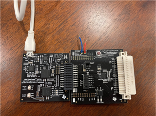
I am trying to use the CAPTIVATE-FR2633 development board to output a PWM signal with a variable duty cycle, and I have a few questions:
- The documentation states that there are 5 general purpose I/O ports that are available to an application (link). The following description is given for the FR2633 board:
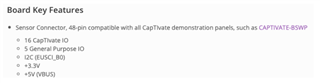
Which are the five GPIO pins? This is not made explicit.
- If I understand correctly, the MSP430 which is used on the development board has four pins which can output PWM signals (P1.1, P1.2, P1.4, and P1.5). Can any of these be used, or would it need to be one of the five GPIO pins asked about above?
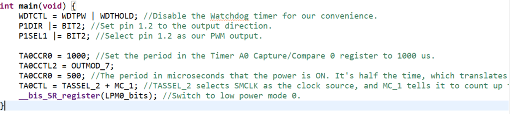
- The code used to output a PWM signal is given below:
#include <msp430.h>
int main(void) {
WDTCTL = WDTPW + WDTHOLD
P1DIR |= BIT2; //Set pin 1.2 to the output direction.
P1SEL0 |= BIT2; //Select pin 1.2 as our PWM output.
TA0CCR0 = 1000; //Set the period in the Timer A0 Capture/Compare 0 register to 1000 us.
TA0CCTL1 = OUTMOD_7;
TA0CCR1 = 500; //The period in microseconds that the power is ON. It's half the time, which translates to a 50% duty cycle.
TA0CTL = TASSEL_2 + MC_1; //TASSEL_2 selects SMCLK as the clock source, and MC_1 tells it to count up to the value in TA0CCR0.
__bis_SR_register(LPM0_bits); //Switch to low power mode 0.
}
Does this code appear correct? We have tried running it, but have not been able to measure a square wave.
- Where on the development board can we measure the PWM output using an oscilloscope for example?
- Would it be possible to output a bipolar square wave with the MSP430? Would this be a software or hardware solution?
Thank you.