This thread has been locked.

If you have a related question, please click the "Ask a related question" button in the top right corner. The newly created question will be automatically linked to this question.

MSP430F2132: IO signal changes, slow response of internal registers and interrupts

Part Number: MSP430F2132

Hello!

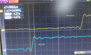
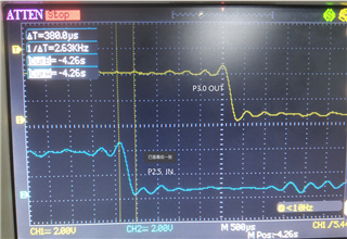
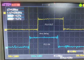
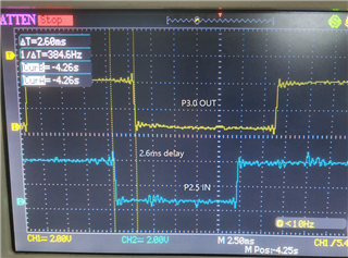
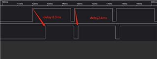
I need to output IO signal or PWM immediately when the input IO signal changes. However, it is found that the response delay is severe, about 1.4-6ms。

simple.The code is as follows:

void main(void)
{

  WDTCTL = WDTPW + WDTHOLD; // Stop WDT

    P2DIR|=BIT5;
   // P2REN&=~BIT5;
    P2IES&=~BIT5;
    P2OUT&=~BIT5;
    P2IFG&=~BIT5;
    P2DIR&=~BIT5;
    //P2IE|=BIT5;


    //p3.0 trigger out
    P3DIR |= BIT0;
    //P3REN|=BIT0;

    while(1){
        if(P2IN&BIT5) //p2.5: mcu-triggerIn
          {
            P3OUT|=BIT0;
          }else{
            P3OUT&=~BIT0;
          }
    }

}

or

void main(void)
{

  WDTCTL = WDTPW + WDTHOLD; // Stop WDT

   //P2.5 interrupt
    P2DIR|=BIT5;
   // P2REN&=~BIT5;
    P2IES&=~BIT5;
    P2OUT&=~BIT5;
    P2IFG&=~BIT5;
    P2DIR&=~BIT5;
    //P2IE|=BIT5;


    //p3.0 trigger out
    P3DIR |= BIT0;
    //P3REN|=BIT0;

    _EINT();
    __low_power_mode_1();
}


//mcu-triggerin
#pragma vector=PORT2_VECTOR  
__interrupt void Port_2(void)
{ 

  P2IFG&=~(BIT5 | BIT4);
  if(P2IN&BIT5) //p2.5: mcu-triggerIn
  { 
    P3OUT|=BIT0;
    P2IES|=BIT5;

  }else{
      P3OUT&=~BIT0;
      P2IES&=~BIT5;
  }

}

The logic levels of input and output ports are monitored externally, and the delay is found, and the delay time is related to the duty cycle of input level and long waiting time.

I think the possible reasons are:
1) The external input level changes and it is slow to update the internal pin register
2) The change from output IO to drive IO level is slow

  • Hello Jun Zhang,

    To get a faster response time, increasing the CPU speed will reduce the latency of the response. Also, it would be recommended to use the interrupt version versus the polling version. This will allow the program to react faster with the ISR instead of having to react when it reaches that specific line of code in the polling version.

    sincerely,

    Luke

  • I don't doubt the speed of MCU code execution. The dominant frequencies of 1m and 16m are the same. The delay time between input level and output level is large(1.5ms ~ 8ms)
    I suspect one or two of the following:
    1) After the input level changes, the change delay of the driving pin register
    2) After the pout register value changes, the drive output level is delayed

  • The delay time between input level and output level is large(1.5ms ~ 8ms)

    Your (assumed LSA) capture of the input and output signals doesn't show the rise and fall times of the input signal.

    Have you got an oscilloscope as that would allow the rise and fall times to be seen? Possibly a slow rise or fall time could explain the apparent delay.

    Also, what device is the source of the input signal?

    Looking at the code I can't see anything which explains the delay.

  • thanks

    the source of the input signal:Other MSP430 periodically output signals

    P2.5 input change, synchronous output P3.0 through IO interrupt

    P2.5 rise time ≈  P3.0  rise time =380us

    P2.5 fall time ≈  P3.0  fall time =370us

    p2.5 rise - p3.0 rise  delay:4ms

    p2.5 fall - p3.0 fall  delay:2.6ms

    
    void main(void)
    {
    
      WDTCTL = WDTPW + WDTHOLD; // Stop WDT
    
    
        P2DIR|=BIT5;
        //P2REN&=~BIT5;
        P2OUT&=~BIT5;
        P2IFG&=~BIT5;
        P2DIR&=~BIT5;
        P2IES&=~BIT5;
        P2IE|=BIT5;
    
    
        //p3.0 trigger out
        P3DIR |= BIT0;
        P3OUT&=~BIT0;
        
        _EINT();
        //__low_power_mode_1();
    }
    
    
    //mcu-triggerin
    #pragma vector=PORT2_VECTOR  
    __interrupt void Port_2(void)
    { 
    
      P2IFG&=~BIT5;
      if(P2IN&BIT5) //p2.5: mcu-triggerIn
      { 
        P3OUT|=BIT0;
        P2IES|=BIT5;
    
      }else{
          P3OUT&=~BIT0;
          P2IES&=~BIT5;
      }
    
    }

  • Thank Chester Gillon

    After changing the input IO port, it is found that the response is fast. After analysis, it turns out that pin2.5 has a large capacitance filter. After adjustment, the reaction time is fast.

**Attention** This is a public forum