This thread has been locked.

If you have a related question, please click the "Ask a related question" button in the top right corner. The newly created question will be automatically linked to this question.

MSP-EXP430FR2433: Design Flaw for S3

Part Number: MSP-EXP430FR2433
Other Parts Discussed in Thread: MSP430FR2433

I've discovered a design flaw in this board. When you are trying to debug an ISR which is bound to the RST/NMI pin while in NMI mode, the target's PC gets loaded with the wrong address and forces a crash. The PC should be getting loaded with the address to the ISR.

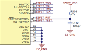
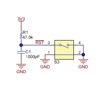
This is the cause. Switch S3 is connected to the RST/NMI pin on the emulator chip and the target chip. So when you close the switch, the emulator chip senses a reset signal while the target chip senses a NMI.

The target chip will only properly execute the ISR after the program is loaded and the debugger is closed.

Are you guys aware of this?

  • Hi Thomas,

    The S3 in FR2433 launch pad only connect to MSP430FR2433 RST pin. You could see the schematic in the user's guide

    https://www.ti.com/lit/ug/slau739/slau739.pdf?ts=1628141434034&ref_url=https%253A%252F%252Fwww.ti.com%252Ftool%252FMSP-EXP430FR2433

    FR2433 RST pin has another function that is SBWTDIO, the emulator will communication by this pin, So when you press the S3 it will influence the communication of emulator.

  • Yes, I saw that before I made my post, but I wasn't confident as to whether RST and EZFET_RST were the same signal or not.

    I came across this problem when testing the following code. It configures the RST/NMI pin to NMI mode and the LED at P1.0. The interrupt is supposed to toggle the LED. When I put a break point inside of the ISR, run the program, and press S3, the program crashes and CCS give me this message:

    Break at address "0x4" with no debug information available, or outside of program code.

    I also see the PC is loaded with 0x4, which isn't right.

    But when I load the program, exit CCS debug mode, and then press S3, the ISR properly executes. Do you know why CCS crashes when the breakpoint is in this ISR?

    .

    #include <msp430.h> 
    int main(void)
    {
        WDTCTL = WDTPW + WDTHOLD;
        SFRRPCR |= SYSNMI;
        SFRRPCR |= SYSNMIIES;
        SFRIE1  |= NMIIE;
        P1DIR |= BIT0;
        P1OUT &= ~BIT0;
        PM5CTL0 &= ~LOCKLPM5;
        LPM0;
        return 0;
    }
    #pragma vector = UNMI_VECTOR
    __interrupt void UNMI_ISR(void){
        if ((SFRIFG1 & NMIIFG) == BIT4){
            P1OUT ^= BIT0;
            SFRIFG1 &= ~NMIIFG;
        }
        if ((SFRIFG1 & OFIFG) == BIT1){}
    }
    

  • Hi Thomas,

    In Debug mode Pin function is SBWTDIO, reset and NMI not work. If you press S3 it will disturb the communication.

  • Thank you for explaining the S3 function.

    Since that interferes with and is in conflict with testing the RST/NMI pin while in NMI mode, I would like to see that fixed for the next revision of that board.

  • There is nothing to fix without de-multiplexing the signals from the pin. To debug while using the interrupt, you will need an alternate form of debugging like the back channel serial.

**Attention** This is a public forum