This thread has been locked.

If you have a related question, please click the "Ask a related question" button in the top right corner. The newly created question will be automatically linked to this question.

MSP-FET: Migrating from 1.4a to 2.0+ MSP-FET

Part Number: MSP-FET
Other Parts Discussed in Thread: UNIFLASH, MSP430FR5739, MSP-TS430RHA40A

Hello,

I have been tasked with moving from the old 1.4a MSP-FET to the new 2.0+ version.

Everything works fine, except when I go to read from the device, despite using the -a and -n flag on the MSP430Flasher.exe same as before,
it triggers a reset where the old debugger does not.

The MSP430Flasher lists "attempting read without reset" for both.

It is undesirable for this state to change for my application.

Is this a known issue?

  • Hi Stefan,

    Sorry, I don't understand your question.

    You encounter the download issue when using MSP-FET? -a, -n flag means what?

    Thanks!

    Best Regards

    Johnson

  • The flags refer to the MSP430Flasher utility where -n is supposed to allow you to select the device type, and -a is unintrusive target connection (which requires -n from what I have read).

    Using the older style 1.4a MSP-FET I can read without a reset occurring, but when I switch to the newer 2.0 MSP-FET, the reset occurs before read for some reason despite identical commands.

    All firmware and software has been checked and is up to date. 

  • Hi Stefan,

    Got your feedback, I will touch MSP-FET expert to check if have this problem.

    And another question:

    How did you see the hardware version for MSP-FET?

    Thanks!

    Best Regards

    Johnson

  • Sorry for the delayed response.

    I have the original boxes that came with the devices that list the model.

    It appears to only reset when attempting to read. This is using just SBW and not JTAG. I am getting the same behavior across several different MSP430 dev boards, so it is not isolated.

  • Hi Stefan,

    Have you updated MSP430Flasher to the latest version for testing?

    There may be have some compatible problem between software and hardware.
    And dose this abnormal reset will affect your application?

    Maybe you can also try to download using Uniflash tool, this is the latest burning tool.

    Thanks!

    Best Regards

    Johnson

  • Yes, everything in on the latest version.

    If the device resets, so does the code, which affects the operation unfortunately.

    I will try the Uniflash tool, though is there a way to use this in the command line? I need to be able to automate the programming.

  • Hi Stefan,

    Uniflash support command line.

    Thanks!

    Best Regards

    Johnson

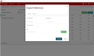
  • Finally got Uniflash installed and tried using the command line. I am able to flash, and technically read, but I really need the exported file to be readable in ti-txt format like the file I'm loading. Is there a way to convert the data? I'm only seeing options for binary and coff.

  • Hi Stefan,

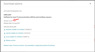
    Please download the lastest version uniflash, this be able to export TI-TXT format:

    https://www.ti.com/tool/UNIFLASH?keyMatch=&tisearch=search-everything&usecase=software#downloads

    Thanks!

    Best Regards

    Johnson

  • Ok. Just to clarify and update.

    I am using Uniflash 6.4 with both MSP-FET 1.4a and 2.0+. The chip is a MSP430FR5739 and socket board is MSP-TS430RHA40A. All jumpers are in correct mode for SBW.

    I am able to use everything on Uniflash GUI and script.

    What I was referring to, is there is no ti-txt output option for dslite gui memory mode. I did however write my own python script to convert the .bin data to a similar format, but I think this option being missing is a pretty big oversight since this is supposed to replace MSP430Flasher which does have this option.

    The real issue is that regardless of Uniflash GUI, script, or MSP430Flasher.exe, the MSP-FET 2.0+ is causing the device to reset each time I read using SBW (2-wire JTAG). The exact same scripts and procedures on MSP-FET 1.4a does not cause this issue. If 2.0 is supposed to be better, why is it causing this issue?

    Again, this is on multiple boards and chips, with multiple programmers, on multiple computers, all running the latest software and drivers, so this is not due to a defective board or programmer.

    Edit:

    Not sure if this is the cause, but I put an oscilloscope on VCC (VCC_TOOL from MSP-FET), TCK, and TDI/TDO and the difference between the signals seems to be there is a brief voltage drop to about 0.3V on TCK and VCC before each read on the MSP-FET 2.0+, but does not occur on the MSP-FET 1.4a.

    My hypothesis is this was enough to power cycle the device, however I also ran external 3.3V to ensure there was no power cycle, and observed the same reset behavior and TCK voltage drop.

    Would this brief drop of voltage on TCK cause this reset? And if so, why is this happening on the MSP-FET2.0? There is obviously some brief power drop on the MSP-FET side since it's VCC_TOOL voltage drops.

    Unfortunately I do not have the ability to post the oscilloscope waveforms at the moment, but this should be able to be replicated on your side.

  • Update: I did a few studies to determine regular behavior and the results are as follows:

    MSP-FET 1.4a ext power: no reset

    MSP-FET 1.4a int power: no reset

    MSP-FET 2.0+ ext power: no reset

    MSP-FET 2.0+ int power: reset

    I also noticed previously that the power on MSP-FET 2.0+ int power cycles right before a read so I'm 90% sure that's why it resets.

    This did not explain the entire situation however so I got rid of the ribbon cable between the MSP-FET and MSP-TS430RHA40A and replaced it with standard single wires with dupont connectors so I could debug.

    I then went wire by wire removing them until the behavior changed. After much trial and error I found that the TEST/VPP pin 8 caused both devices both ext and int power to reset when removed.

    With this discovery I hooked up my oscilloscope to the TEST/VPP pin 8, TDO/TDI pin 1, and TCK pin 7 and observed the above behavior both with TEST/VPP pin 8 connected and disconnected. These were the results:

    MSP-FET 1.4a ext power w/ TEST: no reset

    MSP-FET 1.4a ext power w/o TEST: reset

    MSP-FET 1.4a int power w/ TEST: no reset

    MSP-FET 1.4a int power w/o TEST: reset

    MSP-FET 2.0+ ext power w/ TEST: no reset

    MSP-FET 2.0+ ext power w/o TEST: reset

    MSP-FET 2.0+ int power w/ TEST: reset

    MSP-FET 2.0+ int power w/o TEST: reset

    On the oscilloscope, for both ext and int w/ TEST, the TCK pin 7 signal had strange "steps" in the pattern that did not exist w/o TEST.

    Those "steps" did however correspond exactly to a signal on TEST/VPP pin 8 from the MSP-FET and voltage was pulled lower when the signal was low, acting as a voltage divider would.

    I then repeated this on multiple computers, with multiple different devices, with multiple MSP-FETs of both types and repeatedly got the same results.

    Conclusion:

    There is a signal on TCK/VPP pin 8 that does something strange to the TCK pin 7 which causes it to not reset (my desired outcome), and when not present, it resets on read.

    While this "technically" "fixes" the issue, this raises more questions and concerns that need addressing.

    1. If according to the documentation, the TEST/VPP is for security fuse burn, why am I seeing this signal when I do not have that option set, and what about it causes the device to not reset?

    2. Why is the documentation completely wrong about this signal, and the behavior of these products.

    3. Why on internal power does the MSP-FET 2.0+ drop before a read? This is completely unacceptable!

    4. Why has no one else figured this out yet?

  • 1. If according to the documentation, the TEST/VPP is for security fuse burn, why am I seeing this signal when I do not have that option set, and what about it causes the device to not reset?

    I haven't yet attempted to trace the operation, but looking at the MSPFlasher_1.3.20 source code I can't see any call to MSP430_Configure (INTERFACE_MODE) which I think means the MSP-FET will be left using AUTOMATIC_IF which may drive TEST/VPP as part of the automatic selection between 4 Wire JTAG / 2 Wire SBW.

    Some 4 Wire JTAG devices with multiplexed JTAG pins require the TEST pin.

    Perhaps modifying the MSPFlasher source code to an add an option to control the interface selection would help.

    4. Why has no one else figured this out yet?

    In theory all the source code for the MSP430 DLL in the PC and firmware in the MSP-FET is open source and available.

  • I did not know the code was open. I will have to take a look to see if there's a permanent way to fix this that doesn't require hardware changes.

    The two biggest questions that I have though that remains are:

    1. What about this "stepped" signal makes it that the device does not reset. Or maybe an even better question, what exactly about TCK signal causes the device to reset?

    2. Why does the MSP-FET 2.0+ int power suddenly power cycle before a read?

    Maybe both of these questions lie in the code somewhere. I will try to find the source, however this goes a bit beyond my limited coding knowledge, so someone with a bit more experience may be required to get to the bottom of this.

  • Just to clear up things from target device (FR5739) side. For SBW interface on target device are used only TEST (SBW_TCK) and RESET (SBW_TDIO) pins, with connected ground, and VCC from target or master side. By VCC is powered one side of voltage translators at FET output (14-pin connector).

    For SBW interface between MSP-FET master and FRAM target are used pins 1, 2 or 4, 7 and 9 on FET 14-pin connector. Other pins on FET 14-pin connector (including pin 8 TEST/VPP) should be disconnected. It is Fig 2.3 in slau278 (MSP430 Hardware Tools User's Guide).

  • Thank you for the information.

    I fully understand what the "intended" setup is from the user guides.

    To put things plainly, hooking up the "intended" way does not work. It causes a device reset on read.

    Adding Pin 8 TEST jumpered to Pin 7 TCK as it is on all dev boards, works and doesn't reset the device on read because of what I'm understanding is an unintentional signal on TEST.

    I am assuming this is why this hasn't been discovered sooner as most programmers probably don't care about the reset, or are using dev boards that unintentionally "solve" this. For custom hardware however, this falls apart. 

    In order to correct the behavior and remove TEST pin 8 from the equation to return to "intended" setup however, what needs to be understood is:

    1. What about this overlapping signal causes the behavior of no reset (desired)

    2. What about the non-overlapping signal causes the behavior of reset (not desired)

    3. What in the code is causing TEST in the first place?

    As referenced above, the second reset issue is why is the MSP-FET 2.0+ in internal (power from VCC_TOOL) mode cutting briefly right before read?

    One of two paths can be taken from here:

    1. We give up on actually fixing the issue the right way and just update the user guides so the next poor soul coming after me doesn't have to go through this nightmare.

    2. We find out what causes the behaviors and why my "workaround" works and actually fix this on the code level.

  • Hi Stefan,

    It seems that you have done a lot of research here.

    Now, the main problem is that it is not clear why the MSP-FET 2.0 has a power cycle before reading. I will try to reproduce the problem on my side, and then try to diagnosis the root cause.

    Thanks!

    Best Regards

    Johnson

  • Thank you for your help in the matter.

    As far as the other reset on read without power cycle, I think has to do with the JTAG initialization sequence, which using an oscilloscope seems correct without the TEST/VPP signal.

    With the TEST/VPP signal attached to TCK, it is causing issues with the JTAG initialization somehow, but I don't understand from the datasheets for JTAG how this is causing the device to not reset, or how the device even selects SBW correctly with this signal being disrupted?

    I saw reference to a reset of the JTAG state machine during initialization, but I doubt this has anything to do with reset of the actual device unless somehow resetting that state machine is causing the state machine on the MSP to reset as well? Either way, I think this initialization signal is the culprit. I just do not understand the coding of the low level JTAG interface well enough to figure anything out.

    But agreed, most troubling is why the MSP-FET 2.0 is power cycling on internal power mode. Look forward to seeing your outcome.

  • Perhaps modifying the MSPFlasher source code to an add an option to control the interface selection would help.

    Attached is a modified MSP430Flasher.exe, along with the modified source based upon v1.3.20, which adds a new option:

     -m JTAG |                   Configure interface protocol used.
        SPYBIWIRE |              JTAG: : The normal standard 4-wire JTAG
        SPYBIWIREJTAG |                  communication.
        AUTOMATIC                SPYBIWIRE : Spy-bi-Wire (2-wire) JTAG protocol
                                 SPYBIWIREJTAG: Standard 4-wire JTAG communication
                                                for MSP430 devices which also
                                                support Spy-bi-Wire (a special
                                                entry sequence is needed to switch
                                                these MSP430 derivatives into
                                                4-wire mode which cannot be applied
                                                to any MSP430 devices)
                                 AUTOMATIC: JTAG communication protocol is selected
                                            automatically by the  MSPDdebugStack

    Would be interesting to see if using -m SPYBIWIRE changes the behavior.

    MSP430Flasher.zip

    Source.zip

  • Chester. Thank you for the help. It might take a day or two before I have time to try this, but as soon as I'm able, I will report the findings.

    Out of curiosity, on a side note, does Uniflash use MSP430Flasher as a base? I noticed these files floating around in some folder when I exported a .zip from uniflash. Or is this just the old support commands that were referenced in the manual?

  • I think Uniflash should not based on MSP430Flasher. 

    Does you try the file provide by chester? Is there other question?

    Thanks!

  • So. I modified my test code to increment every time the device boots and store in fram so I can better characterize the issue.

    What I found is that without TEST/VPP connected, on the original MSPFlasher, it resets twice somehow. With the new MSPFlasher with -m SPYBIWIRE selected it only resets once, and with old MSPFlasher with TEST/VPP connected I get no resets.

    I believe this supports my theory this is somehow resetting based on the initialization sequence, I just don't know enough about the low-level code to understand why that is happening.

  • Hi Stefan,

    I agree with you, but I am not the erpert, and I try to understand this issue and learn the low-level code, but no any progress.

    I can feedback this to other team and try to see if there is some progress。

    Thanks!

    Best Regards

    Johnson

  • Johnson,

    Thank you for your help. I completely understand. I will continue to try things myself and see what I can come up with. Please keep me posted. Thanks again.

  • Got it, thanks! I will let you know if I get any update from other team.

**Attention** This is a public forum