


Hello,
I am having issues with the duty cycle generated in my code. I am using this code in my power converter but in this case, I am just giving a fixed duty cycle value and only turning on the gate driver supply (not running the converter). However, I am getting random variations in the duty cycle, even though it is fixed, which I believe is why I am having spikes when running the converter in closed loop. I have inserted below a snippet of my main code and the functions I am using to set period and duty cycle.
I am eliminating sub-sections of the code and trying to figure out where the problem is. What didn't make sense to me is that the code runs fine when I am just setting duty cycle values and calling the function, but adding the line of code " Vbuck_new=3;" gives me the random switching.
    while (1){
        /*
        P1OUT = 0b0;
        adc_chan=7;
        ADC10MCTL0 = (ADC10MCTL0 & ~ADC10INCH_1) | ADC10INCH_7;
        GetADC(); // Vin_temp

        Vin_3=Vin_2;
        Vin_2=Vin_1;
        Vin_1=Vin_0;
        Vin_0=Vin_temp;
        Vin=(Vin_0+Vin_1+Vin_2+Vin_3)>>2;
        __delay_cycles(10);
        __no_operation();

        Vin_new=Vin/52;
        */

        Vbuck_new=3; //Vbuck_temp/57;

        D_buckH=85;//333*(Vbuck_new/Vin_new);

        if (D_buckH>280){
            D_buckH=280;
        }

        else if (D_buckH<75){
            D_buckH=75;
        }

        D_buckL=D_buckH+1;

        __delay_cycles(10);                   // Delay between sequence convs

        SetDuty_Buck (D_buckH, D_buckL);
        __no_operation();

    }


    void SetPWM(unsigned int tbuck, unsigned int tboost){
    // Configure TimerD in Hi-Res Regulated Mode - for TD0
    TD0CTL0 = TDSSEL_2;                    // TDCLK=SMCLK=25MHz=Hi-Res input clk select
    TD0CTL1 |= TDCLKM_1;                   // Select Hi-res local clock
    TD0HCTL1 |= TDHCLKCR;                  // High-res clock input >15MHz
    TD0HCTL0 = TDHM_0 +                    // Hi-res clock 8x TDCLK = 200MHz
            TDHREGEN +                     // Regulated mode, locked to input clock
            TDHEN;                         // Hi-res enable

    // Configure TimerD in Hi-Res Regulated Mode - for TD1
    TD1CTL0 = TDSSEL_2;                    // TDCLK=SMCLK=25MHz=Hi-Res input clk select
    TD1CTL1 |= TDCLKM_1;                   // Select Hi-res local clock
    TD1HCTL1 |= TDHCLKCR;                  // High-res clock input >15MHz
    TD1HCTL0 = TDHM_0 +                    // Hi-res clock 8x TDCLK = 200MHz
            TDHREGEN +                     // Regulated mode, locked to input clock
            TDHEN;                         // Hi-res enable

    while(!TDHLKIFG);                      // Wait until hi-res clock is locked -  frequency lock Interrupt Flag
    TD0CTL0 |= TDCLR;                      // Reset timer for TD1
    TD0CCR0 = tbuck;                       // Period Register - 200MHz/(100kHz)= 2000 - using high resolution clock
    TD1CTL0 |= TDCLR;                      // reset timer for TD1
    TD1CCR0 = tboost;                      // Period Register - 200MHz/(100kHz)= 2000 - using high resolution clock
}

void SetDuty_Buck (unsigned int dbuckH, unsigned int dbuckL) {
    TD0CTL0 |= TDCLR;                      // reset timer for TD1
    TD0CCTL1 |= OUTMOD_2 + CLLD_2;           // CCR1 toggle/reset
    TD0CCR1 = dbuckH;                         // CCR1 PWM duty cycle of 1000/2000 = 50%
    TD0CCTL2 |= OUTMOD_6 + CLLD_2;           // CCR2 toggle/set
    TD0CCR2 = dbuckL;                         // CCR2 PWM duty cycle of 500/2000 = 25%
    TD0CTL0 |= MC_3 + TDCLR;                 // up/down-mode, clear TDR, Start timer

}
The first two figures below show the switching waveforms and the last one is the voltage transient that happens because of this random switching.
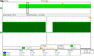
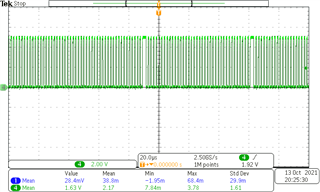
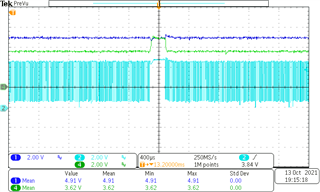
Thank you.
