This thread has been locked.

If you have a related question, please click the "Ask a related question" button in the top right corner. The newly created question will be automatically linked to this question.

MSP430FR2512: Problem with I2C in Design Center, no "HID connected" seen

Part Number: MSP430FR2512
Other Parts Discussed in Thread: CAPTIVATE-PGMR, EVM430-CAPMINI, MSP430FR2522, MSP430FR2633, MSP430FR2533, MSP430FR2532, MSP430FR2632

Hello,

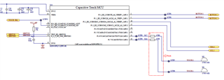
I use a custom board for the MSP430FR2512 where I have setup SBW and I2C to the Captivate-PGMR, 2 self buttons, I can generate the source code and set a break point which breaks when there is a touch and or prox.

So I know the software works.

However, I cannot for the life of me connect it to Design center to tune the measurements.

I have followed the quick start to the spot where it says:

Start HID communication with the target

Enable the HID communication by selecting the menu “Communications->Connect.” Verify the HID device is connected by viewing the message in the main window lower left corner.

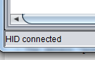
Fig. 141 HID Connection Status

Yeah, no such thing, I have a version number down there, never a ready or hid connected, even using the EVM430-CAPMINI prior to the custom board (but it used UART) which reads values of UART fine. 

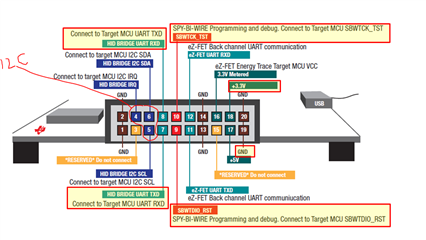
I am now using I2C, it should not cause any issues, but it appears it does.

I am reusing a pre-existing I2C-bus (currently no other IC's connected to it, just test pads and pull-ups 4k7) and I do not have the pins to set up a UART just for this.

When I click connect in the communications menu, it does not say anything and I can not read any values.

So before you kindly divert me to the quick start guide,  tell me first where the "HID-connected"-note is.


Best regards,

Sebastian

  • I go through the CAPT_BSP.C looking for clues (I use MSP430FR2512IPW16R now, in the EVM430-CAPMINI it is of course the 20-pin QFN, but the pinout seems to be wrong, does the BSP have support for the TSSOP model?

  • Hi Sebastian,

    What pins on the FR2512 are you trying to use for communicating with the GUI? If you are using I2C, the default pins are P1.2 and P1.3.  You will also need to select an IRQ pin to use.  You can select the pin in the CAPT_commConfig.h file.  Make sure you configure these pins in the BSP.c file according to their function (PSEL registers).

  • SDA = P1.2, SCL = P1.3, IRQ = 2.1 (due to layout reasons, but reconfigured in CAPT_commConfig.h as you say), do I need to change something in the BSP as well? 

    As per the other post, https://e2e.ti.com/support/microcontrollers/msp-low-power-microcontrollers-group/msp430/f/msp-low-power-microcontroller-forum/969610/msp430fr2512-bulk_i2c-available:

    It appears to be insufficient support of the TSSOP version.

    Best regards,

    Sebastian

  • Hi Sebastian,

    Yes, you need to set the P1SEL.2 = 1 and P1SEL3 bits = 0 accordingly.

    .

    According to the datasheet, P1.2, P1.3 are available as I2C pins.  You don't need to change USCIBRMP, so you should be good.

    Make sure you are connecting to the I2C pins on the CAPT-PGMR and that you are using __CAPT_BULKI2C_INTERFACE__ in your CAPT_Userconfig.h

    When using the GUI, make sure you also select the BULKI2C connection option.

  • So, just to make sure :

    SYSCFG2 |= USCIBRMP;

    // P1.0: OUTPUT LOW
    // P1.1: OUTPUT LOW
    // P1.2: OUTPUT LOW
    // P1.3: OUTPUT LOW
    // P1.4: UCA0 UART TXD if (DEFAULT_OSC_SELECTION == CS_XT1CLK_SELECT), else OUTPUT LOW
    // P1.5: UCA0 UART RXD if (DEFAULT_OSC_SELECTION == CS_XT1CLK_SELECT), else OUTPUT LOW
    // P1.6: OUTPUT LOW
    // P1.7: OUTPUT LOW
    #if (DEFAULT_OSC_SELECTION == CS_XT1CLK_SELECT)
    P1OUT = (0);
    P1DIR = (GPIO_PIN0 | GPIO_PIN1 | GPIO_PIN2 | GPIO_PIN3 | GPIO_PIN6 | GPIO_PIN7);
    P1SEL0 = (GPIO_PIN4 | GPIO_PIN5);
    P1SEL1 = (0);
    #else
    P1OUT = (0);
    P1DIR = (GPIO_PIN0 | GPIO_PIN1 | GPIO_PIN4 | GPIO_PIN5 | GPIO_PIN6 | GPIO_PIN7);
    P1SEL0 = (GPIO_PIN2 | GPIO_PIN3);
    P1SEL1 = (0);

    Is this correct?

  • Thanks for the response.

    So, I made a brand new project in design center for the MSP430FR2512IPW16R, 2 simple self buttons, i2c bulk.

    They are connected to cap0.2 and cap0.3, i have IRQ on P2.1, wake up on prox, LPM3, force LPM4 in wake on prox.

    CAPT_CommConfig.h

    #ifdef __MSP430FR2522__ // MSP430FR2522
    #define I2CSLAVE__REQ_POUT (P2OUT)
    #define I2CSLAVE__REQ_PDIR (P2DIR)
    #define I2CSLAVE__REQ_MASK (BIT4)
    #else // MSP430FR2633, MSP430FR2533, MSP430FR2632, MSP430FR2532
    #define I2CSLAVE__REQ_POUT (P2OUT)
    #define I2CSLAVE__REQ_PDIR (P2DIR)
    #define I2CSLAVE__REQ_MASK (BIT1)
    #endif

    CAPT_BSP.c

    #if (DEFAULT_OSC_SELECTION == CS_XT1CLK_SELECT)
    P1OUT = (0);
    P1DIR = (GPIO_PIN0 | GPIO_PIN1 | GPIO_PIN2 | GPIO_PIN3 | GPIO_PIN6 | GPIO_PIN7);
    P1SEL0 = (GPIO_PIN4 | GPIO_PIN5);
    P1SEL1 = (0);
    #else
    P1OUT = (0);
    P1DIR = (GPIO_PIN0 | GPIO_PIN1 ); //two outputs for setting button state, similar to LED on captivate-mini
    P1SEL0 = (0);
    P1SEL1 = (GPIO_PIN2 | GPIO_PIN3);
    #endif

    #if (DEFAULT_OSC_SELECTION == CS_XT1CLK_SELECT)
    P2OUT = (GPIO_PIN4);
    P2DIR = (GPIO_PIN2 | GPIO_PIN3 | GPIO_PIN4);
    P2SEL0 = (0);
    P2SEL1 = (GPIO_PIN0 | GPIO_PIN1 | GPIO_PIN5 | GPIO_PIN6);
    #else
    P2OUT = (GPIO_PIN1);
    P2DIR = (GPIO_PIN1);
    P2SEL0 = (0);
    P2SEL1 = (0);
    #endif

    I set a break point on I2CSlave_setRequestFlag, it triggers during wake up from prox.

    Only released from time out, never read.

    I have tripple checked wiring, continuity checked and check for correct pulls.

    I also hooked up the UART and tested it using the captivate-mini SW, it works, but I want the i2c to work.

    If you do believe I have done something wrong, please generate a project, adjust the bsp and commconfig and send back to me .

    Best regards,

    Sebastian

  • Hi Sebastian,

    Not exactly - see the table above for eUSCIB0?  In order to use P1.2, P1.2 you want SYSCF2 &= ~USCIBRMP.  By default, this bit is cleared at POR.  SYSCFG2 |= selects eUSCIB0 but on pins P2.5, P2.6.

    Regarding the I2CSlave_setRequestFlag, once this is set by the software, the host (CAPT-PGMR) must respond to the interrupt and start an I2C bus transaction to read the data, else the I2CSlave driver's timeout will reset the bus.  If you are not seeing this activity then make sure in the GUI you select BULKI2C and click the CONNECT button.  This will send a command down to the CAPT-PGMR to switch to I2C mode.  Do you have an o-scope or logic probe to check the SDA and SCL lines?  Verify they are pulled up to 3.3v.

    Looking at your schematic, I would use the following assignments in your BSP.C

        // P1.0: INPUT
        // P1.1: INPUT
        // P1.2: UCB0 I2C SDA
        // P1.3: UCB0 I2C SCL
        // P1.4: OUTPUT LOW
        // P1.5: OUTPUT LOW
        // P1.6: INPUT (CAP0.2)
        // P1.7: INPUT (CAP0.3)
        P1OUT  = (0);
        P1DIR  = (GPIO_PIN4 | GPIO_PIN5);
        P1SEL0 = (GPIO_PIN2 | GPIO_PIN3);
        P1SEL1 = (0);

        // P2.0: OUTPUT LOW
        // P2.1: IRQ (OPEN DRAIN)
        // P2.2: OUTPUT LOW
        P2OUT  =  (0);
        P2DIR  =  (GPIO_PIN0 | GPIO_PIN2);
        P2SEL0 =  (0);
        P2SEL1 =  (0);

    I also notice in your schematic that you have a 4.7uF connected to VREG?  This must be a 1.0uF only.

  • // Re-map EUSCI B0 pins to secondary locations
    // This frees up CapTIvate IOs
    //
    SYSCFG2 &= ~USCIBRMP;
    // SYSCFG2 |= USCIBRMP;

    // P1.0: OUTPUT LOW
    // P1.1: OUTPUT LOW
    // P1.2: OUTPUT LOW

    I did this now, did nothing.

**Attention** This is a public forum