This thread has been locked.

If you have a related question, please click the "Ask a related question" button in the top right corner. The newly created question will be automatically linked to this question.

MSP430F449: The MSP430F449 LC displays abnormality, after power down and power back up, it's normal

Part Number: MSP430F449

Hi team,

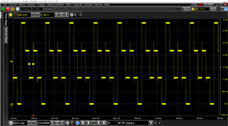
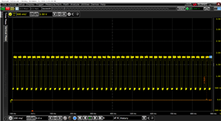
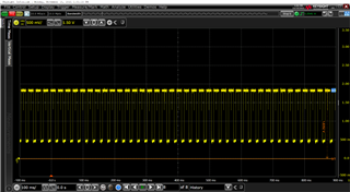
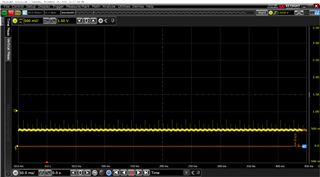
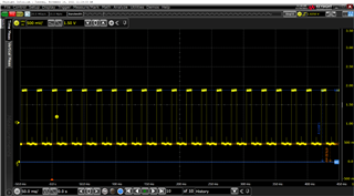
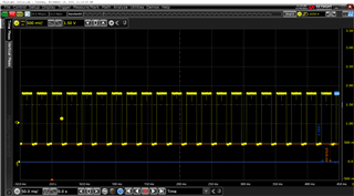
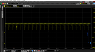
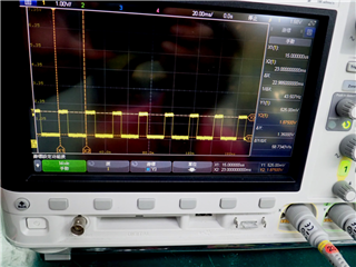
The MCU operates at 3.3V, but only has a voltage waveform of about 1.8V, and the LCD is very attenued and requires a certain angle to see the residual image. The part that needs to be displayed as a number also shows the non-numeric exception. And when the power is disconnected and then restored, the LCD display goes off and the display returns to normal.

Issues:

1. Does the MSP430F449 have this kind of bug in the LCD driver module?

2. 2.Why does the total power supply disconnect and then power back up to return to normal? The power supply is a 3.6V battery, and it's all new, and it has both an LDO and tantalum capacitance and MLCC regulation and filtering on the circuit. The customer would like to know is there anything else could be wrong?

Could you help check this case? Thanks.

Best Regards,

Cherry

  • Hi Cherry,

    Let's test some items so we can narrow down what the issue is.

    Have they tested the example code Example 1, Example 2, Example 3? This will help us narrow down if its a software or a hardware issue.

    1. We don't have any verified errata's with the LCD on that device.

    2. A full reset could be resetting various registers that aren't getting properly reset otherwise, if we can verify that the example code works it can assist us in going into taking the next step into the code. If the example code doesn't work we need to look at the hardware system.

    Regards,

    Luke

  • Hi Luke,

    The code in the LCD section is ok, because it is normal after burning(LCD drive waveform, operating voltage 3.3V).

    After burning, all functions (LCD display, GPIO function, communication function) are OK, and the operating voltage of the MCU is 3.3V, the LCD also has a normal drive waveform (as shown on the left below), but some of the results will be raised to 500mV, with the highest point being just about 2V drive waveform (as shown on the right below).

    However, the MCU's voltage is 3.27V, and the current consumption is increased to 10mA, and it will returns to normal as long as cut the power supply (operating voltage 3.3V, power consumption is restored to normal power saving mode IQ: 200uA or less).

    Could you help check this issue?

    Thanks and Best Regards,

    Cherry

  • Those waveforms look very similar to the ones detailed in the user's guide.

    Though the offset of the second image is very strange.

    Can you help clarify the system that they are using?

    • Are they using a Mux or a static format? If mux, which mux mode?
    • Is this happening across one segment or every segment?
    • If the issue gets fixed on a power cycle is there a set amount of time that passes before the issue appears or is it on a startup?
  • Hi Luke,

    Thanks for your reply!

    Are they using a Mux or a static format? If mux, which mux mode?

    They are using 3-Mux mode.

    Is this happening across one segment or every segment?

    The LCD basically has a strange output for each pin, either COM or segment. As shown in the figure below, the waveforms are all in the states below and the voltage amplitude is similar.

    If the issue gets fixed on a power cycle is there a set amount of time that passes before the issue appears or is it on a startup?

    Removing and then reconnecting the power supply (3.6V battery) will restore, and basically, once the power supply is connected, it will not be disconnected, but the register will be repeated periodically. But the problem is not all, but probability, about 2% of the anomalies, And the anomalies are similar.

    Thanks and Best Regards,

    Cherry

  • Hi Cherry,

    We have a couple theories in mind but we need to ask more clarifying questions so we can narrow down the issue further.

    1. Does any other reset fix the issue momentarily? Like triggering the reset pin while keeping the board powered.
    2. When they used the demo code did this issue appear at around the same time?
    3. Can they time how long it takes for the error state to appear when they reconnect power? You can send us the waveform of it going from power up to the correct state to the error state.
    4. Once it is in the error state does it stay there until a power cycle happens? or does the system resolve itself?

    Regards,

    Luke

**Attention** This is a public forum