This thread has been locked.

If you have a related question, please click the "Ask a related question" button in the top right corner. The newly created question will be automatically linked to this question.

MSP-EXP430G2ET: program issue

Part Number: MSP-EXP430G2ET
Other Parts Discussed in Thread: UNIFLASH

Hi team,

I find someone has a similar issue with MSP-EXP430G2ET.

https://e2e.ti.com/support/microcontrollers/msp-low-power-microcontrollers-group/msp430/f/msp-low-power-microcontroller-forum/937683/msp-exp430g2et-error-could-not-set-device-vcc

But my customer could not solve it, could you please help to find the issue my customer has?


Below is step my customer do.

Open UniFlash:


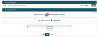
  1. Detect device => Manual ( It seems “Auto” can’t fine device)


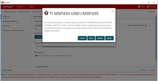
  1. Choose Your device => TI MSP430G2ET and Click “Start”
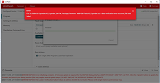


  1. Load image:

Am I right to use IO_Expander.txt for loading images?


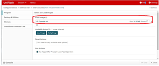
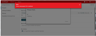
  1. After I click “Load Image” or “Verify Image”, the GUI shows:


  • Hi Jason,

    On the auto detect, does the device show up under the device manager under the COM Ports? If the device isn't in the device manager we will have to solve that first.

    For the DS property there have been a couple different solutions to that particular issue.

    1. Is the system on Windows 10 or an older version of windows?
      1. User's have reported issues with Windows 7
    2. Have you tried running the application as admin?
    3. Are you running on the cloud or an installed version, if installed is it the most updated version?
      1. Does the same issue appear on the command line interface version of Uniflash?
    4. Sometimes a corporate network can block Uniflash, try testing it off network.
    5. Here is another potential solution where the timeout had to be increased due to some network settings, Past Thread.

    Here is another thread that has a bunch potential solutions and some more details on the potential cause, Uniflash DS Issue.

    Regards,

    Luke

  • Hi Luck,

    I told my customer your suggestions, but there is another issue occurs.

    update:

    1. On the auto detect, does the device show up under the device manager under the COM Ports? Yes. UniFlash still can’t find device by auto on windows 10

     2.Change system to windows 10 (The original one is win7)

    • Use the same step.
    •  After click “load image” (there is no “Cannot read property DS of undefined” now), the image can be loaded and then show an another error message:
    • Click “Update” directly (there is no network on this system) => System seems to start to update fw but shows an error message:

      3. Power off the device and do the “load image” produce again. Now the console of UniFlash shows”[Success] Program Load completed successfully”

      4.Try to control the IO-Expander by GUI.
      • Try to turn on or off the LED(D1,D2,D3 and D4) but there is no anything happened on these LEDs.
  • We solved the initial DS issue which is good (looks like changing to Windows 10 fixed it), the on board ez-FET needed to be updated (that was done in your last image of 2), but it looks like the program was flashed successfully.

    I think the current issue is either a hardware or GUI configuration.

    I would walk through the User's guide again to make sure that the jumper pins are in the correct place, and that the other GUI options are selected correctly. There seems to be an error with the link to the zip file, but an E2E post contains the zip file for the program. IO Expander EVM Zip file.

    If you need to adjust the source code, the zip file has the source code as well and you can look at it through CCS (Code Composer Studio).

    Regards,

    Luke

  • Hi Luke,

    SLVUA59A is not using MSP-EXP430G2ET to demo.
    SLVUA59A is using MSP-EXP430G2. So the pin assignment is different when my customer reading this document. 

    The code is the same on TI.com website? 


    Jason

  • Hi Luke,

    Do you know how to solve this issue?

    Jason

  • The MSP-EXP430G2ET should be working with the same code, the ET device is the same MCU with some improvements to the board which added energy trace (hence the ET ending), a new debugger (therefore there were jumper block changes), and some minor improvements.

    Comparing the 2 boards the jumper blocks 1 and 2 are identical, which are the blocks that the EVM connects to. The P1.6 is on the right side of the board near j2 and looks to be unpopulated in the document. P1.0 is still populated and can be found on the left side near j1.

    On jumper block 101 (the eZ-FET jumper block), keep all the pins connected to their counter part on the other side of the board (so vertical orientation) but, connect the RX to the TX of the same side (horizontal orientation).

    Regards,

    Luke

**Attention** This is a public forum