This thread has been locked.

If you have a related question, please click the "Ask a related question" button in the top right corner. The newly created question will be automatically linked to this question.

MSP430FR2433: I2C communication

Part Number: MSP430FR2433

I am trying to send data from my STM32H7 board (Master) to my MSP430FR2433 (Slave) through I2C but with no luck.

I tried to imitate the MSP430 Master-Tx example code into the STM32 and I tested it on Arduino and it works. Also, I'm sure my MSP430 Slave-Rx code is correct, I tested it by sending data from another MSP430 and it works.

Any suggestions on what the problem could be?

  • Some suggestions to you: 1.Check your clock, whether the slave's clock is provided by the master ;2. Check whether I2C communication rate of master and slave keep the same; 3. Check your slave address and register address, are there any gap between MSP430 and STM?

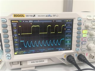
    It's better for you to use an oscilloscope to catch the wave and see whether it meets the requirement from slave. You can show the waveform if not be solved. 

  • The thing is that communication is successful between STM32-Arduino and Arduino-MSP430, but not STM32-MSP430

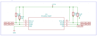
  • Could you upload your code example and hardware schematic diagram?

  • Hello Sherman, this is what I'm getting from the oscilloscope 

  • This is my STM32 schematic, I2C1 part 

    and these are each of the MSP and STM32 codes

    MSP_Code.txt
    #include <driverlib.h>
    #include <msp430.h>
    #include <stdio.h>
    
        const uint16_t interrupts = EUSCI_B_I2C_RECEIVE_INTERRUPT0;
        volatile uint32_t i;
        volatile uint8_t Rxbuf[5];
        volatile uint8_t status;
    
    int main(void){
    
        WDT_A_hold(WDT_A_BASE);                                                    // Stop watchdog timer
    
        GPIO_setAsOutputPin(GPIO_PORT_P1, GPIO_PIN0 + GPIO_PIN1);                  // Set P1.0 + 1.1 to output direction - LED1 + LED2
        GPIO_setAsOutputPin(GPIO_PORT_P1, GPIO_PIN6);                              // Set P1.6 to output - Standby1
        GPIO_setAsOutputPin(GPIO_PORT_P2, GPIO_PIN7);                              // Set P2.7 to output - Reset1
        GPIO_setAsOutputPin(GPIO_PORT_P2, GPIO_PIN6);                              // Set P2.6 to output - Standby2
        GPIO_setAsOutputPin(GPIO_PORT_P2, GPIO_PIN5);                              // Set P2.5 to output - Reset2
        GPIO_setOutputLowOnPin(GPIO_PORT_P1, GPIO_PIN0 + GPIO_PIN1);               // Set LEDs to low
        GPIO_setAsInputPinWithPullUpResistor(GPIO_PORT_P2, GPIO_PIN1);             // Set P2.1 to input  - Button
        // Set P1.2 to input  - i2c_SDA & P1.3 to input  - i2c_SCL
        GPIO_setAsPeripheralModuleFunctionInputPin(GPIO_PORT_P1, GPIO_PIN2 + GPIO_PIN3, GPIO_PRIMARY_MODULE_FUNCTION);
    
        // Disable the GPIO power-on default high-impedance mode to activate previously configured port settings
        PMM_unlockLPM5();
    
        EUSCI_B_I2C_initSlaveParam initSlaveParam = {0};
        initSlaveParam.slaveAddress = 0x48;
        initSlaveParam.slaveAddressOffset = EUSCI_B_I2C_OWN_ADDRESS_OFFSET0;
        initSlaveParam.slaveOwnAddressEnable = EUSCI_B_I2C_OWN_ADDRESS_ENABLE;
        EUSCI_B_I2C_initSlave(EUSCI_B0_BASE, &initSlaveParam);
    
        EUSCI_B_I2C_setMode(EUSCI_B0_BASE, EUSCI_B_I2C_RECEIVE_MODE);
    
        EUSCI_B_I2C_enable(EUSCI_B0_BASE);
    
        EUSCI_B_I2C_clearInterrupt(EUSCI_B0_BASE, interrupts);
    
        EUSCI_B_I2C_enableInterrupt(EUSCI_B0_BASE, interrupts);                    // receive interrupt enable
    
        GPIO_setOutputLowOnPin(GPIO_PORT_P1, GPIO_PIN6);
        __delay_cycles(1000);
        GPIO_setOutputHighOnPin(GPIO_PORT_P1, GPIO_PIN6);                          // Standby board 1
    
        __delay_cycles(5000000);
    
        GPIO_setOutputLowOnPin(GPIO_PORT_P2, GPIO_PIN7);                           // Reset board 1
        GPIO_setOutputHighOnPin(GPIO_PORT_P2, GPIO_PIN7);
    
        __bis_SR_register(CPUOFF + GIE);
        __no_operation();
    
    }
    
    #if defined(__TI_COMPILER_VERSION__) || defined(__IAR_SYSTEMS_ICC__)
    #pragma vector=USCI_B0_VECTOR
    __interrupt
    #elif defined(__GNUC__)
    __attribute__((interrupt(USCI_B0_VECTOR)))
    #endif
    void USCIB0_ISR(void)
    {
        switch(__even_in_range(UCB0IV, USCI_I2C_UCBIT9IFG))
        {
            case USCI_NONE:             // No interrupts break;
                break;
            case USCI_I2C_UCALIFG:      // Arbitration lost
                break;
            case USCI_I2C_UCNACKIFG:    // NAK received (master only)
                break;
            case USCI_I2C_UCSTTIFG:     // START condition detected with own address (slave mode only)
                break;
            case USCI_I2C_UCSTPIFG:     // STOP condition detected (master & slave mode)
                break;
            case USCI_I2C_UCRXIFG3:     // RXIFG3
                break;
            case USCI_I2C_UCTXIFG3:     // TXIFG3
                break;
            case USCI_I2C_UCRXIFG2:     // RXIFG2
                break;
            case USCI_I2C_UCTXIFG2:     // TXIFG2
                break;
            case USCI_I2C_UCRXIFG1:     // RXIFG1
                break;
            case USCI_I2C_UCTXIFG1:     // TXIFG1
                break;
            case USCI_I2C_UCRXIFG0:     // RXIFG0
                Rxbuf[0] = UCB0RXBUF; //EUSCI_B_I2C_slaveGetData(EUSCI_B0_BASE);
                if(Rxbuf[0]){
                    GPIO_setOutputHighOnPin(GPIO_PORT_P1, GPIO_PIN1);
                }
                break;
            case USCI_I2C_UCTXIFG0:     // TXIFG0
                break;
            case USCI_I2C_UCBCNTIFG:    // Byte count limit reached (UCBxTBCNT)
                break;
            case USCI_I2C_UCCLTOIFG:    // Clock low timeout - clock held low too long
                break;
            case USCI_I2C_UCBIT9IFG:    // Generated on 9th bit of a transmit (for debugging)
                break;
            default:
                break;
        }
    }
    
    STM_Code.txt
    /* USER CODE BEGIN Header */
    /**
     *
     * This program takes the mcu to standby mode and wakes it up from it.
     *
      ******************************************************************************
      * @file           : main.c
      * @brief          : Main program body
      ******************************************************************************
      * @attention
      *
      * <h2><center>&copy; Copyright (c) 2021 STMicroelectronics.
      * All rights reserved.</center></h2>
      *
      * This software component is licensed by ST under BSD 3-Clause license,
      * the "License"; You may not use this file except in compliance with the
      * License. You may obtain a copy of the License at:
      *                        opensource.org/licenses/BSD-3-Clause
      *
      ******************************************************************************
      */
    /* USER CODE END Header */
    /* Includes ------------------------------------------------------------------*/
    #include "main.h"
    
    /* Private includes ----------------------------------------------------------*/
    /* USER CODE BEGIN Includes */
    #include <stdio.h>
    #include <string.h>
    /* USER CODE END Includes */
    
    /* Private typedef -----------------------------------------------------------*/
    /* USER CODE BEGIN PTD */
    
    /* USER CODE END PTD */
    
    /* Private define ------------------------------------------------------------*/
    /* USER CODE BEGIN PD */
    /* USER CODE END PD */
    
    /* Private macro -------------------------------------------------------------*/
    /* USER CODE BEGIN PM */
    
    /* USER CODE END PM */
    
    /* Private variables ---------------------------------------------------------*/
    
    I2C_HandleTypeDef hi2c1;
    
    UART_HandleTypeDef huart1;
    
    /* USER CODE BEGIN PV */
    
    /* USER CODE END PV */
    
    /* Private function prototypes -----------------------------------------------*/
    void SystemClock_Config(void);
    static void MX_GPIO_Init(void);
    static void MX_USART1_UART_Init(void);
    static void MX_I2C1_Init(void);
    /* USER CODE BEGIN PFP */
    
    /* USER CODE END PFP */
    
    /* Private user code ---------------------------------------------------------*/
    /* USER CODE BEGIN 0 */
    
    uint8_t buf[50];
    uint8_t Txbuf[50];
    
    //Button: GPIOC(PE4) interrupt
    void HAL_GPIO_EXTI_Callback(uint16_t GPIO_Pin){
    	// Entering Standby mode
    	sprintf((char*)buf, "\rEntering Standby mode \n");
    	HAL_UART_Transmit(&huart1, buf, strlen((char*)buf), 100);
    
    	__HAL_PWR_CLEAR_FLAG(PWR_FLAG_WKUP1);
    
    	HAL_GPIO_WritePin(GPIOB, LED1_Pin, GPIO_PIN_SET);
    
    	HAL_PWR_EnableWakeUpPin(PWR_WAKEUP_PIN1);
    
    	sprintf((char*)buf, "\rStandby mode ON \n");
    	HAL_UART_Transmit(&huart1, buf, strlen((char*)buf), 100);
    
    	HAL_PWR_EnterSTANDBYMode();
    }
    
    /* USER CODE END 0 */
    
    /**
      * @brief  The application entry point.
      * @retval int
      */
    int main(void)
    {
      /* USER CODE BEGIN 1 */
    
      /* USER CODE END 1 */
    
      /* MCU Configuration--------------------------------------------------------*/
    
      /* Reset of all peripherals, Initializes the Flash interface and the Systick. */
      HAL_Init();
    
      /* USER CODE BEGIN Init */
    
      /* USER CODE END Init */
    
      /* Configure the system clock */
      SystemClock_Config();
    
      /* USER CODE BEGIN SysInit */
    
      /* USER CODE END SysInit */
    
      /* Initialize all configured peripherals */
      MX_GPIO_Init();
      MX_USART1_UART_Init();
      MX_I2C1_Init();
      /* USER CODE BEGIN 2 */
    
      static const int addr = 0x48 << 1;
      Txbuf[0] = 1;
    
      // Waking up from Standby mode
      sprintf((char*)buf, "\rWakeup\n\n");
      HAL_UART_Transmit(&huart1, buf, strlen((char*)buf), 100);
    
      __HAL_PWR_CLEAR_FLAG(PWR_FLAG_SB);
    
      for(int i=0; i<30; i++){
    	  HAL_GPIO_TogglePin(GPIOB, LED1_Pin);
    	  HAL_Delay(100);
      }
    
      HAL_PWR_DisableWakeUpPin(PWR_WAKEUP_PIN1);
    
      /* USER CODE END 2 */
    
      /* Infinite loop */
      /* USER CODE BEGIN WHILE */
      while (1)
      {
    
    	  HAL_GPIO_WritePin(GPIO_F_FCC_GPIO_Port, GPIO_F_FCC_Pin, GPIO_PIN_SET);							//Enable I2C
    	  HAL_I2C_Master_Transmit(&hi2c1, addr, (uint8_t *)Txbuf, 1, 100);
    
    	  sprintf((char*)buf, "\rData sent!\n");
    	  HAL_UART_Transmit(&huart1, buf, strlen((char*)buf), 100);
    
    	  HAL_Delay(5000);
    
        /* USER CODE END WHILE */
    
        /* USER CODE BEGIN 3 */
      }
      /* USER CODE END 3 */
    }
    
    /**
      * @brief System Clock Configuration
      * @retval None
      */
    void SystemClock_Config(void)
    {
      RCC_OscInitTypeDef RCC_OscInitStruct = {0};
      RCC_ClkInitTypeDef RCC_ClkInitStruct = {0};
    
      /** Supply configuration update enable
      */
      HAL_PWREx_ConfigSupply(PWR_LDO_SUPPLY);
      /** Configure the main internal regulator output voltage
      */
      __HAL_PWR_VOLTAGESCALING_CONFIG(PWR_REGULATOR_VOLTAGE_SCALE3);
    
      while(!__HAL_PWR_GET_FLAG(PWR_FLAG_VOSRDY)) {}
      /** Initializes the RCC Oscillators according to the specified parameters
      * in the RCC_OscInitTypeDef structure.
      */
      RCC_OscInitStruct.OscillatorType = RCC_OSCILLATORTYPE_HSI;
      RCC_OscInitStruct.HSIState = RCC_HSI_DIV1;
      RCC_OscInitStruct.HSICalibrationValue = RCC_HSICALIBRATION_DEFAULT;
      RCC_OscInitStruct.PLL.PLLState = RCC_PLL_NONE;
      if (HAL_RCC_OscConfig(&RCC_OscInitStruct) != HAL_OK)
      {
        Error_Handler();
      }
      /** Initializes the CPU, AHB and APB buses clocks
      */
      RCC_ClkInitStruct.ClockType = RCC_CLOCKTYPE_HCLK|RCC_CLOCKTYPE_SYSCLK
                                  |RCC_CLOCKTYPE_PCLK1|RCC_CLOCKTYPE_PCLK2
                                  |RCC_CLOCKTYPE_D3PCLK1|RCC_CLOCKTYPE_D1PCLK1;
      RCC_ClkInitStruct.SYSCLKSource = RCC_SYSCLKSOURCE_HSI;
      RCC_ClkInitStruct.SYSCLKDivider = RCC_SYSCLK_DIV1;
      RCC_ClkInitStruct.AHBCLKDivider = RCC_HCLK_DIV1;
      RCC_ClkInitStruct.APB3CLKDivider = RCC_APB3_DIV1;
      RCC_ClkInitStruct.APB1CLKDivider = RCC_APB1_DIV8;
      RCC_ClkInitStruct.APB2CLKDivider = RCC_APB2_DIV2;
      RCC_ClkInitStruct.APB4CLKDivider = RCC_APB4_DIV1;
    
      if (HAL_RCC_ClockConfig(&RCC_ClkInitStruct, FLASH_LATENCY_1) != HAL_OK)
      {
        Error_Handler();
      }
    }
    
    /**
      * @brief I2C1 Initialization Function
      * @param None
      * @retval None
      */
    static void MX_I2C1_Init(void)
    {
    
      /* USER CODE BEGIN I2C1_Init 0 */
    
      /* USER CODE END I2C1_Init 0 */
    
      /* USER CODE BEGIN I2C1_Init 1 */
    
      /* USER CODE END I2C1_Init 1 */
      hi2c1.Instance = I2C1;
      hi2c1.Init.Timing = 0x2000090E;
      hi2c1.Init.OwnAddress1 = 0;
      hi2c1.Init.AddressingMode = I2C_ADDRESSINGMODE_7BIT;
      hi2c1.Init.DualAddressMode = I2C_DUALADDRESS_DISABLE;
      hi2c1.Init.OwnAddress2 = 0;
      hi2c1.Init.OwnAddress2Masks = I2C_OA2_NOMASK;
      hi2c1.Init.GeneralCallMode = I2C_GENERALCALL_DISABLE;
      hi2c1.Init.NoStretchMode = I2C_NOSTRETCH_DISABLE;
      if (HAL_I2C_Init(&hi2c1) != HAL_OK)
      {
        Error_Handler();
      }
      /** Configure Analogue filter
      */
      if (HAL_I2CEx_ConfigAnalogFilter(&hi2c1, I2C_ANALOGFILTER_ENABLE) != HAL_OK)
      {
        Error_Handler();
      }
      /** Configure Digital filter
      */
      if (HAL_I2CEx_ConfigDigitalFilter(&hi2c1, 0) != HAL_OK)
      {
        Error_Handler();
      }
      /* USER CODE BEGIN I2C1_Init 2 */
    
      /* USER CODE END I2C1_Init 2 */
    
    }
    
    /**
      * @brief USART1 Initialization Function
      * @param None
      * @retval None
      */
    static void MX_USART1_UART_Init(void)
    {
    
      /* USER CODE BEGIN USART1_Init 0 */
    
      /* USER CODE END USART1_Init 0 */
    
      /* USER CODE BEGIN USART1_Init 1 */
    
      /* USER CODE END USART1_Init 1 */
      huart1.Instance = USART1;
      huart1.Init.BaudRate = 115200;
      huart1.Init.WordLength = UART_WORDLENGTH_8B;
      huart1.Init.StopBits = UART_STOPBITS_1;
      huart1.Init.Parity = UART_PARITY_NONE;
      huart1.Init.Mode = UART_MODE_TX_RX;
      huart1.Init.HwFlowCtl = UART_HWCONTROL_NONE;
      huart1.Init.OverSampling = UART_OVERSAMPLING_16;
      huart1.Init.OneBitSampling = UART_ONE_BIT_SAMPLE_DISABLE;
      huart1.Init.ClockPrescaler = UART_PRESCALER_DIV1;
      huart1.AdvancedInit.AdvFeatureInit = UART_ADVFEATURE_NO_INIT;
      if (HAL_UART_Init(&huart1) != HAL_OK)
      {
        Error_Handler();
      }
      if (HAL_UARTEx_SetTxFifoThreshold(&huart1, UART_TXFIFO_THRESHOLD_1_8) != HAL_OK)
      {
        Error_Handler();
      }
      if (HAL_UARTEx_SetRxFifoThreshold(&huart1, UART_RXFIFO_THRESHOLD_1_8) != HAL_OK)
      {
        Error_Handler();
      }
      if (HAL_UARTEx_DisableFifoMode(&huart1) != HAL_OK)
      {
        Error_Handler();
      }
      /* USER CODE BEGIN USART1_Init 2 */
    
      /* USER CODE END USART1_Init 2 */
    
    }
    
    /**
      * @brief GPIO Initialization Function
      * @param None
      * @retval None
      */
    static void MX_GPIO_Init(void)
    {
      GPIO_InitTypeDef GPIO_InitStruct = {0};
    
      /* GPIO Ports Clock Enable */
      __HAL_RCC_GPIOE_CLK_ENABLE();
      __HAL_RCC_GPIOH_CLK_ENABLE();
      __HAL_RCC_GPIOB_CLK_ENABLE();
      __HAL_RCC_GPIOD_CLK_ENABLE();
    
      /*Configure GPIO pin Output Level */
      HAL_GPIO_WritePin(LED1_GPIO_Port, LED1_Pin, GPIO_PIN_RESET);
    
      /*Configure GPIO pin Output Level */
      HAL_GPIO_WritePin(GPIO_F_FCC_GPIO_Port, GPIO_F_FCC_Pin, GPIO_PIN_RESET);
    
      /*Configure GPIO pin : PE4 */
      GPIO_InitStruct.Pin = GPIO_PIN_4;
      GPIO_InitStruct.Mode = GPIO_MODE_IT_RISING;
      GPIO_InitStruct.Pull = GPIO_PULLDOWN;
      HAL_GPIO_Init(GPIOE, &GPIO_InitStruct);
    
      /*Configure GPIO pin : LED1_Pin */
      GPIO_InitStruct.Pin = LED1_Pin;
      GPIO_InitStruct.Mode = GPIO_MODE_OUTPUT_PP;
      GPIO_InitStruct.Pull = GPIO_NOPULL;
      GPIO_InitStruct.Speed = GPIO_SPEED_FREQ_LOW;
      HAL_GPIO_Init(LED1_GPIO_Port, &GPIO_InitStruct);
    
      /*Configure GPIO pin : GPIO_F_FCC_Pin */
      GPIO_InitStruct.Pin = GPIO_F_FCC_Pin;
      GPIO_InitStruct.Mode = GPIO_MODE_OUTPUT_PP;
      GPIO_InitStruct.Pull = GPIO_NOPULL;
      GPIO_InitStruct.Speed = GPIO_SPEED_FREQ_LOW;
      HAL_GPIO_Init(GPIO_F_FCC_GPIO_Port, &GPIO_InitStruct);
    
      /* EXTI interrupt init*/
      HAL_NVIC_SetPriority(EXTI4_IRQn, 0, 0);
      HAL_NVIC_EnableIRQ(EXTI4_IRQn);
    
    }
    
    /* USER CODE BEGIN 4 */
    
    /* USER CODE END 4 */
    
    /**
      * @brief  This function is executed in case of error occurrence.
      * @retval None
      */
    void Error_Handler(void)
    {
      /* USER CODE BEGIN Error_Handler_Debug */
      /* User can add his own implementation to report the HAL error return state */
      __disable_irq();
      while (1)
      {
      }
      /* USER CODE END Error_Handler_Debug */
    }
    
    #ifdef  USE_FULL_ASSERT
    /**
      * @brief  Reports the name of the source file and the source line number
      *         where the assert_param error has occurred.
      * @param  file: pointer to the source file name
      * @param  line: assert_param error line source number
      * @retval None
      */
    void assert_failed(uint8_t *file, uint32_t line)
    {
      /* USER CODE BEGIN 6 */
      /* User can add his own implementation to report the file name and line number,
         ex: printf("Wrong parameters value: file %s on line %d\r\n", file, line) */
      /* USER CODE END 6 */
    }
    #endif /* USE_FULL_ASSERT */


  • Hello, it seems that problem happens on SCL line. You can check the clock of master first, if no problem, you can try two ways below: 

    1.Reduce the pull-up register to 2.2k or 3.3kΩ.   2.Optimize the connection style between two boards to reduce parasitic capacitance

**Attention** This is a public forum