This thread has been locked.

If you have a related question, please click the "Ask a related question" button in the top right corner. The newly created question will be automatically linked to this question.

MSP430FR2476: msp430fr2476

Part Number: MSP430FR2476
Other Parts Discussed in Thread: MSP430FR5972, MSP430G2955

HI Jace

I want to return on my problem with I2Cbus on the microcontroller MSP430FR2476, as I wrote some times ago, there is a problem

and is impossible to enable this port on the UCB1.

I would like to precise that I using the I2CBus on the others item without any problem.

For all this Time, I had no time to finish this work but now need finish it, adn using the same controller onother equipment.

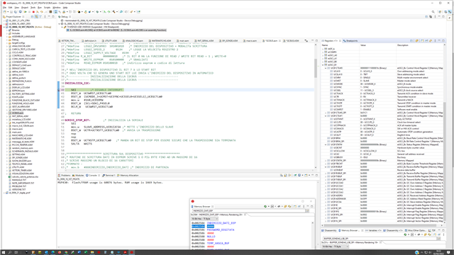
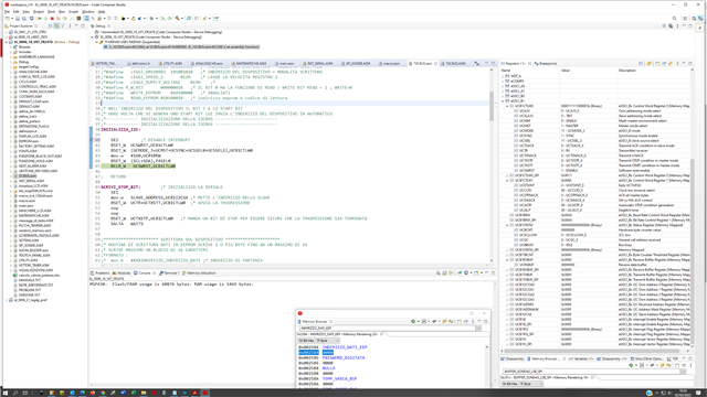
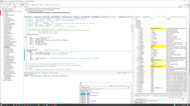
Really the problem is no the I2cbus but the inizialitation, I using the same routine from long time on different items withou any problem,
when I chang the Item only adapt the registers.

On the Msp430FR2476 when I set the initialization register is set the bit Busy and is impossible to use the I2cbus.

This on the UCB1 and UCB0 only for the I2cbus, because with SPI work properly. I have tested only UCB1 on SPI.

I have try all the following configuration ad when set  bic.b #UCSWRST,UCB1CTL1 immediately is set the BUSYU bit into the UCB1STATW

and is impossible to use the I2Cbus.

FIRST OF ALL  BSET_W, BCLR_W, BSET_B, BCLR_B are all macro 

BSET_W .macro par0,par1
             bisx.w #par0,par1
              .endm

BCLR_W .macro par0,par1
            bicx.w #par0,par1 ; *
           .endm 

BSET_B .macro par0,par1
             bisx.b #par0,par1
              .endm

BCLR_B .macro par0,par1
            bicx.b #par0,par1 ; *
           .endm 

Configuration on your data sheet 

UCBxCTL1 |= UCSWRST; // eUSCI_B in reset state
UCBxCTLW0 |= UCMODE_3; // I2C slave mode
UCBxI2COA0 = 0x0012; // own address is 12hex
P2SEL |= 0x03; // configure I2C pins (device specific)
UCBxCTL1 &= ^UCSWRST; // eUSCI_B in operational state
UCBxIE |= UCTXIE + UCRXIE; // enable TX&RX-interrupt
GIE; // general interrupt enable

I don't use the interrupt in this case and is Master mode 


this configuration work Properly on the MSP430FR5972  and do not work on the MSP430FR2476 

           bis.w        #UCSWRST,UCB0CTLW0 
           BSET_W  ( UCMODE_3+UCMST+UCSYNC),UCB0CTLW0 
           MOV.W      #I2SPEED_100KHZ,UCB0BRW 
           BCLR_W  UCSWRST,UCB0CTLW0 

this configuration work Properly on the MSP430G2955  and do not work on the MSP430FR2476 

          BSET_B  UCSWRST,UCB0CTL1 
          BSET_B  (UCMODE_3+UCMST+UCSYNC),UCB0CTL0 
          BSET_B  UCMODE_3,P3SEL 
          MOV.B     #I2SPEED_100KHZ_LSB,UCB0BR0 
          MOV.B     #I2SPEED_100KHZ_MSB,UCB0BR1
          BSET_B  (UCSSEL0+UCSSEL1),UCB0CTL1
          BCLR_B  UCSWRST,UCB0CTL1

So I have made many possible configuration and following there are the example tested 

all configuration when reset the bit UCSWRST,UCB0CTL1 immediately trigger the BUSY bit and is not possible to reset this bit more. 

           bis.b     #(SCL+SDA),P4SEL0
           bis.w    #UCSWRST,UCB1CTLW0 
           bis.w    #(UCMODE_3+UCMST+UCSYNC+UCSSEL0+UCSSEL1),UCB1CTLW0
           mov.w  #160,UCB1BRW 
           bic.w    #UCSWRST,UCB1CTLW0 

          bis.w      #UCSWRST,UCB1CTLW0 
          bis.w      #(UCMODE_3+UCMST+UCSYNC+UCSSEL0+UCSSEL1),UCB1CTLW0
          mov.w    #160,UCB1BRW 
          bis.b      #(SCL+SDA),P4SEL0
          bis.w     #UCASTP_2,UCB0CTLW1
          bic.w     #UCSWRST,UCB1CTLW0 

in the following case when tryu to set the register with bit method and not with word method nothing ois changed 

on the register 

BSET_B UCSWRST,UCB1CTL1 
BSET_B (UCMODE_3+UCMST+UCSYNC),UCB1CTL0 

MOV.B #160,UCB1BR0 
MOV.B #0,UCB1BR1 
BSET_B (UCSSEL0+UCSSEL1),UCB1CTL1
BSET_B (SCL+SDA),P4SEL0
BCLR_B UCSWRST,UCB1CTL1

------------------------------

bis.b #UCSWRST,UCB1CTL1
bis.w #(UCMODE_3+UCMST+UCSYNC+UCSSEL0+UCSSEL1),UCB1CTLW0 
mov.w #160,UCB1BRW 
bis.b #(SCL+SDA),P4SEL0
bic.b #UCSWRST,UCB1CTL1 

-----------
bis.b #UCSWRST,UCB1CTLW0 
bis.w #(UCMODE_3+UCMST+UCSYNC+UCSSEL0+UCSSEL1),UCB1CTLW0 
mov.w #160,UCB1BRW ;* PRESCALER LSB
bis.b #(SCL+SDA),P4SEL0
bic.b #UCSWRST,UCB1CTLW0 


----------------------------

bis.b #UCSWRST,UCB1CTLW0 
mov.w #(UCMODE_3+UCMST+UCSYNC+UCSSEL0+UCSSEL1+UCSWRST),UCB1CTLW0 
mov.w #160,UCB1BRW 
bis.b #(SCL+SDA),P4SEL0
bic.b #UCSWRST,UCB1CTLW0 

----------------------------
bis.w #UCSWRST,UCB1CTLW0 
mov.b #(UCMODE_3+UCMST+UCSYNC),UCB1CTL1
mov.w #160,UCB1BRW 
bis.b #(SCL+SDA),P4SEL0
bic.w #UCSWRST,UCB1CTLW0 

----------------------------
bis.w #UCSWRST,UCB1CTLW0 
bis.w #(UCMODE_3+UCMST+UCSYNC+UCSSEL0+UCSSEL1+UCTXSTP+UCTXSTT),UCB1CTLW0
mov.w #160,UCB1BRW 
bis.b #(SCL+SDA),P4SEL0
bic.w #UCSWRST,UCB1CTLW0 

----------------------------
bis.w #UCSWRST,UCB1CTLW0 
bis.w #(UCMODE_3+UCMST+UCSYNC+UCSSEL0+UCSSEL1+UCTXSTP+UCTXSTT),UCB1CTLW0
mov.w #160,UCB1BRW 
bis.b #(SCL+SDA),P4SEL0
bis.w #UCTXSTP,UCB1CTLW0
bic.w #UCSWRST,UCB1CTLW0 

----------------------------

bis.b #(SCL+SDA),P4SEL0
bis.w #UCSWRST,UCB1CTLW0 
bis.w #(UCMODE_3+UCMST+UCSYNC+UCSSEL0+UCSSEL1+UCTXSTP+UCTXSTT),UCB1CTLW0
mov.w #160,UCB1BRW 
bis.w #UCTXSTP,UCB1CTLW0
bic.w #UCSWRST,UCB1CTLW0

---------------------------------

bis.w #UCSWRST,UCB1CTLW0
bis.w #(UCMODE_3+UCMST+UCSYNC+UCSSEL0+UCSSEL1+UCTXSTP+UCTXSTT),UCB1CTLW0
mov.w #160,UCB1BRW 
bis.w #UCTXSTP,UCB1CTLW0
bic.w #UCSWRST,UCB1CTLW0 
bis.b #(SCL+SDA),P4SEL0

  • UCBxCTL1 |= UCSWRST; // eUSCI_B in reset state

    That will never work since the reset bit is in CTL0. Also, use "=" instead of "|=" to make sure all the bits are reset before or'ing stuff into it. They aren't all cleared during reset.

  • Hi David 

    sorry But I didn't Understand,

    the UCSWRST is in the register UCB1CTLW0 

    use "=" instead of "|="

    this is example into the data sheet, 

    UCBxCTL1 |= UCSWRST; // eUSCI_B in reset state
    UCBxCTLW0 |= UCMODE_3; // I2C slave mode
    UCBxI2COA0 = 0x0012; // own address is 12hex
    P2SEL |= 0x03; // configure I2C pins (device specific)

    UCBxCTL1 &= ^UCSWRST; // eUSCI_B in operational state

    I program in assembler and I set and reset the bit in assembler see below 

    this is my firmware and assembler manipolation bits

                   bis.w        #UCSWRST,UCB0CTLW0 
                   bis.w        #( UCMODE_3+UCMST+UCSYNC),UCB0CTLW0 
                   MOV.W    #I2SPEED_100KHZ,UCB0BRW 
                   bic.w        #UCSWRST,UCB0CTLW0 

    if I try to set or reset the bit into the register in the byte access and not in word access 

    the byte are not changed 

    example:  

                   bis.b        #UCSWRST,UCB0CTL0 
                   bis.b        #( UCMODE_3+UCMST+UCSYNC),UCB0CTL1   ;* this bit are not changed 
                   MOV.W    #I2SPEED_100KHZ,UCB0BRW 
                   bic.b        #UCSWRST,UCB0CTL0 

    Luigi 

  • bis.b        #( UCMODE_3+UCMST+UCSYNC),UCB0CTL1   ;* this bit are not changed 

    You keep jumping around. In the previous example you wrote to CTL0 but here write just to the lower half of CTL1. Where none of these settings reside. It wouldn't work on CTL0 either since the UCMODE bits are in the upper 8 bits of that register.

    Both CTL0 and CTL1 are 16 bit registers. If for some reason you need to access the upper or lower byte only, the correct symbols to use have an "_L" or "_H" appended.

  • bis.b #(SCL+SDA),P4SEL0

    P4.6/P4.5 refer to UCB0SDA/SCL (assuming .USCIB0RMP=1).  UCB1SDA/SCL are on P3.2/P3.6 (assuming USCIB1RMP=0). [Ref data sheet (SLASEO7C) Tables 9-11 and 9-25]

    Where are your wires connected?

  • DAVID 

    can you send me the example to set up this register ?

    I used the name of the register that are reported on the data sheet, and I have  try to access   in byte and word but is the same 

    the register are defined in the data sheet as following (page 648 SLAU445I)

    00h UCBxCTLW0 eUSCI_Bx Control Word 0 Read/write Word 01C1h Section 24.4.1
    00h UCBxCTL1 eUSCI_Bx Control 1 Read/write Byte C1h
    01h UCBxCTL0 eUSCI_Bx Control 0 Read/write Byte 01h

    I see that  UCBxCTL1 is a lower byte  LSB bit 0-7 

    and  UCBxCTL0 is a higher byte but MSB bit 8-15

     I see now in the file MSp430fr2476.cmd that this register are defined 

    UCA0CTLW0 = 0x0500;
    UCA0CTLW0_L = 0x0500;
    UCA0CTLW0_H = 0x0501;

    and in the file MSp430fr2476.h are define 

    SFR_16BIT(UCB0CTLW0); /* eUSCI_Bx Control Word Register 0 */
    SFR_8BIT(UCB0CTLW0_L);
    SFR_8BIT(UCB0CTLW0_H);

    so the  UCB0CTL1 and UCB0CTL0 are not define anywhere why the compiler don't show the alarm? 

    are define so in the manual normally the manual and the definition have the same name 

    I will try tomorrow to access with  UCA0CTLW0_L ,UCA0CTLW0_H  and see if are ok 

    Thank you 

    Luigi 

  • Bruce 

    The UCB0SDA/SCL is also on the P4.3 SCL   and P4.4 SDA I'm using this port 

  • David 

    I have try again this morning the followig combination without succes, when is enable the I2c 

    immediately is set the Busy Bit 

    if during process before delete the bit  #UCSWRST I delete the bit UCMODE_3 the bit Busy is not 

    set.

    this procedure is also put immediately under the pinout configuration so no other configuration are 

    enabled  

    main_program:

                 movx.w #STACK_POINTER,SP 

                 mov.w #(FRCTLPW+NWAITS_1),FRCTL0
                 mov.w #(FRWPPW+DFWP+PFWP),SYSCFG0 

                  mov.b #10000000b,P1OUT 
                  mov.b #00000000b,P2OUT 
                  mov.b #00000010b,P3OUT 
                  mov.b #00000101b,P4OUT 
                  mov.b #10000110b,P5OUT 
                  mov.b #00000000b,P6OUT 
                  mov.b #11111111b,P1DIR 
                  mov.b #11111111b,P2DIR 
                  mov.b #11111111b,P3DIR 
                  mov.b #11011010b,P4DIR
                  mov.b #01111111b,P5DIR 
                  mov.b #11111111b,P6DIR

     
                  bis.w #UCSWRST,UCB1CTLW0
                  bis.w #(UCMODE_3+UCMST+UCSYNC),UCB1CTLW0_H
                  bis.w #(UCSSEL0+UCSSEL1),UCB1CTLW0_L
                  mov.w #160,UCB1BRW
                  bis.b #(SCL+SDA),P4SEL0
                  bic.w #UCSWRST,UCB1CTLW0

                  bis.w #UCSWRST,UCB1CTLW0
                  bis.b #(UCMODE_3+UCMST+UCSYNC),UCB1CTLW0_H
                  bis.b #(UCSSEL0+UCSSEL1),UCB1CTLW0_L
                  mov.w #160,UCB1BRW
                  bis.b #(SCL+SDA),P4SEL0
                  bic.w #UCSWRST,UCB1CTLW0

                  bis.b #UCSWRST,UCB1CTLW0_L
                  bis.b #(UCMODE_3+UCMST+UCSYNC),UCB1CTLW0_H
                  bis.b #(UCSSEL0+UCSSEL1),UCB1CTLW0_L
                  mov.w #160,UCB1BRW
                  bis.b #(SCL+SDA),P4SEL0
                  bic.b #UCSWRST,UCB1CTLW0_L

    Luigi 

  • I see three slightly different version of init code. All are wrong but which one are you using?

  • If you want to use the P4.3/P4.4 pins for UCB1, you need to set SYSCFG3:USCIB1RMP=1.[Ref data sheet Table 9-11 Note (2) and user guide Table 1-32]

  • hi Bruce 

    done set bit SYSCFG3:USCIB1RMP=1  but nothing is changed , always is switched on the bit Busy 

    can you send me I correct configuretion that you are sure that is correct? 

    I have try a lot of different configuration but nothing, I don't know were is the error 

    Luigi 


  • Hi David 

    I have test all this combination and also the combination on the top but not is changed 

    I have also set the bit SYSCFG3:USCIB1RMP=1 as told me bruce but nothing is changed 

    can you send me I correct configuretion that you are sure that is correct? 

    I have try a lot of different configuration but nothing, I don't know were is the error 

    Luigi 

  • I don't have fix this issue jet have yuo some tested ans sure initialization for I2cbus B1? 

  • I don't have fix this issue jet have yuo some tested ans sure initialization for I2cbus B1? 

  • I pasted your code into the assembly template, and inserted this just before the UCB1 setup (which I expect you already have/don't need):

    SDA	.set BIT4    ; P4.4=UCB1SDA
    SCL	.set BIT3	; P4.3=UCB1SCL
    			bis.w #USCIB1RMP,SYSCFG3  	; Use the P4 pins for UCB1
    			bic.b #(SCL+SDA),P4DIR		; Input again
    			bis.b #(SCL+SDA),P4OUT		; Cheat on
    			bis.b #(SCL+SDA),P4REN		;  the pullups
    			bic.w #LOCKLPM5,PM5CTL0		; Engage GPIOs
    

    If I stop after the setup, the UCB1 registers look normal, and UCBBUSY=0. I'm not sure what we're doing differently.

  • Unsolicited: I also succeeded with this sequence, which I find a little easier to read:

    			  mov.w #(UCSWRST+UCMODE_3+UCMST+UCSYNC+UCSSEL0+UCSSEL1),UCB1CTLW0
                  mov.w #160,UCB1BRW
                  bis.b #(SCL+SDA),P4SEL0
                  bic.w #UCSWRST,UCB1CTLW0
    

  • Hi Bruce 

    I have tested and now working, at the end I think my error was that  during my test, first do not have setting the bit  #USCIB1RMP,SYSCFG3

    and later do not using this sequence mov.w #(UCSWRST+UCMODE_3+UCMST+UCSYNC+UCSSEL0+UCSSEL1),UCB1CTLW0

     I have using this configuration 

    bis.w #USCIB1RMP,SYSCFG3

    bis.w #UCSWRST,UCB1CTLW0

    mov.w #(UCMODE_3+UCMST+UCSYNC+UCSSEL0+UCSSEL1),UCB1CTLW0
    mov.w #160,UCB1BRW
    bis.b #(SCL+SDA),P4SEL0
    bic.w #UCSWRST,UCB1CTLW0

    with this configuration do not work because maybe don't  accept the bis.w #UCSWRST,UCB1CTLW0 separately 

    he work only with following configuration 

    bis.w #USCIB1RMP,SYSCFG3

    mov.w #(UCSWRST+UCMODE_3+UCMST+UCSYNC+UCSSEL0+UCSSEL1),UCB1CTLW0
    mov.w #160,UCB1BRW
    bis.b #(SCL+SDA),P4SEL0
    bic.w #UCSWRST,UCB1CTLW0

    I had try also with this configuration but first do not had changed  the bit #USCIB1RMP,SYSCFG3.

    and when have set I using separate setting of bis.w #UCSWRST,UCB1CTLW0

    I see that this manipolation is ininfluent; anyway I have during the configuration  

    bis.w #USCIB1RMP,SYSCFG3 ; Use the P4 pins for UCB1
    bic.b #(SCL+SDA),P4DIR ; Input again
    bis.b #(SCL+SDA),P4OUT ; Cheat on
    bis.b #(SCL+SDA),P4REN ; the pullups
    bic.w #LOCKLPM5,PM5CTL0 ; Engage GPIOs

    thank you very much for your support 

    Luigi 

  • 1) That first sequence sets UCSWRST in the first instruction, then clears it in the second (and then tries to set some "reset required" fields).

    2) Buried in the sequence I added, I engaged the internal pullups on the I2C pins. In my case, I didn't have a bus (and so no pullups) but the internal ones suffice if your bus is slow and your wires aren't too long. Is it possible one of your bus pullups has come loose?

    I'm glad you got it working.

  • 1) sure yes I know for this reason I using bis.w bic.w instruction 

    bis.w #USCIB1RMP,SYSCFG3

    bis.w #(UCSWRST+UCMODE_3+UCMST+UCSYNC+UCSSEL0+UCSSEL1),UCB1CTLW0

    but at the same not work, but probably when I using this setting not had set the bit  #USCIB1RMP,SYSCFG3, This I had completely forgot 

    2) I have external bus with pullup of  2k2 on the SDA and SCL pin , don't have yet tested this new pcb, but on the old one work at100khz, during my test I have meet 400khz and more without any problem .

    Honestly I don't have test all I2Cbus yet but I see that do not set more the Busy Bit and send out the Stop bit righ.

    I think that work properly now, the sound is good.

    Thank you for your support

    Luigi 


**Attention** This is a public forum