This thread has been locked.

If you have a related question, please click the "Ask a related question" button in the top right corner. The newly created question will be automatically linked to this question.

MSP430FR6007: eUSCI - UART mode - RX stop bits

Part Number: MSP430FR6007

Hi


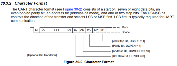
It seems the receiver of the eUSCI in UART mode requires the number of stop bits selected by UCSPB to receive correctly.

Is this correct?


It is not explicit described how the UCSPB setting influence TX and RX individually.

The only reference between RX and stop bits we can find, is in the description of framing error:


“Framing error

UCFE

A framing error occurs when a low stop bit is detected. When two stop bits are used, both

stop bits are checked for framing error. When a framing error is detected, the UCFE bit is set.”


So we can see from the UCFE whether or not the required number of stop bits was received.

But we don’t need to handle framing error in our protocol. It has build in error detection, e.g. by CRC check.


What we see is, that data transmitted with one stop bit is not received correctly.

The first byte is received correctly, but the following ones are incorrect – in a way that could match a delayed reception out of sync.

So it seems that the stop bit setting for the receiver part not only influences the framing error function, but also controls when the receiver is open for a new start edge.


Our protocol specifies two stop bits for transmission. This is only specified to get extra margin for re-synchronization at the next start edge in the receiver.

In the embedded devices we have used in the past (both TI’s and others), the receiver has always only required one stop bit, independent of the UART stop bit setting. E.g. in the USART peripheral of the MSP430x4xx family.

Because our devices interface with a wide range of other devices (both our own and 3rd party, and both embedded and generic devices), some of them only use one stop bit (by mistake or because it can’t be controlled in the specific device). We haven’t been able to control this – and didn’t wanted to, because it worked okay.


If our device TX’s two stop bits and RX’s one stop bit, it can work with all other combinations of one and two stop bits.

If our device TX’s two stop bits and requires two stop bits on RX, it can only work with combinations where the counter part TX’s two stop bits.


We know the “always one RX stop bit” is “text book incorrect”.

But in normal asynchronous communication, it can provide important flexibility and margin.


In our case, we could theoretically try to force all the other devices to follow the protocol to the letter.

But in reality, in many cases we need the backward compatibility because it shall work with exiting devices or with devices that can’t be changed (e.g. if our costumer has bought their own devices from a subcontractor that no longer exists).


Is there anyway this could be changed in existing or upcoming TI devices or families?


We suggest one of the following solutions:

1) The UART RX only checks one stop bit, independent of the UART stop bit setting.

2) The UART could receive a new start edge after maximum 1 stop bit, independent of the UART stop bit setting.

3) The stop bit setting in the UART is split into separate settings for RX and TX.


On our current project, we have the possibility to use two separate eUSCI’s for TX and RX respectively with different stop bit settings. But it means that we will never be able to use the opposite part of each of these interfaces.

In other products we will need more interfaces with this feature, than we can support with two eUSCI’s per interface.


We really hope for a positive answer!

/Mads

  • Hi Mads,

    In short, you can specify one or two stop bits.  If the MSP430 is configured to use 2-stop bits, then it expects the receiving device to receive and send the same 2-stop bits.  Likewise when using 1-stop bit.

    Let me digest your other comments and I will respond.

  • Hi Mads,

    The number of bits in a UART character is defined by one start bit (ST), the # of data bits, # of stop bits (SP) and parity bit (P), ignoring the address bit for this example.  A typical N81 configuration is no PARITY, 8 data bits and 1 stop bit, therefore the UART character is made up of 10 bits:  ST + 8DATA + SP.  This is true for both transmitting and receiving.  The other UART you are communicating with must follow the same character format else you will get framing errors.

    Does this help?

  • The receiver insisting on 2 stop bits seems to be unusual and not at all useful. A check of a couple of old school UARTs (MC68681, 16C550) shows their receivers require only 1 stop bit.

  • Hi Dennis


    Thank you for your answer.


    In short:

    No, these information’s does not help us.


    I fully understand the description. And I know the arguments for that all parts should have the same character format and that the receiver should check for all the bits transmitted.

    It could for instance be relevant if the system/protocol supports multi masters and a check for bus collision is needed.


    BUT – I totally agree with David Schultz!

    I have never before seen a “simple” UART function that checks both stop bits!

    And – as mentioned in my original post – your own older devices (e.g. MSP430F4xx) didn’t check the 2nd stop bit either!


    Single parity bit and multiple stop bits provides a very low protection against bit errors compared to today’s standards.

    On the other hand, more TX stop bits than RX stop bits provides a margin when the receiver shall resynchronize to the start edge of the following start bit, if bytes are transmitted back-to-back.


    For instance, we have seen PC UART’s (especially on laptops) with an extremely poor clock source. Some of them have even been so fare off, that the accumulated edge error exceeds the limit of 50% on the last data bit (equals a clock error above 50% / 1+8 bit ~= 5,5% - a lot compared to typically 20ppm on a 32kHz crystal!!). These cases are a lost cause to cover.

    For counterparts with a clock error below 5,5% (not considering any edge skewness), a strict rule about the same amount of stop bits on both TX and RX would result in the slowest part not being able to catch up with the counterpart, when bytes are transmitted back-to-back. The second byte would be sampled wrong, if the receiver isn’t ready for the start edge and triggers at a later edge.

    In this case, a margin could rescue the situation.

    I understand if this is a major change to your eUSCI module.

    I guess the eUSCI utilizes the same state machine underneath, for both TX and RX!?

    Then it is a structural change to differentiate stop bits on TX and RX when they both are active at the same time.


    Maybe you guys can figure out an easy solution in your architecture, if you look at it this way:

    We don’t necessarily need an extra stop bit on TX – “just” a time margin between back-to-back TX bytes.

    For instance, a solution could be to have a simple delay (maybe configurable) between bytes on TX. The important thing is that RX shall not be influenced by this “TX byte delay”!


    What we need is an answer to the following questions:

    Are you guys actively looking into or at least considering changing this in existing or upcoming TI devices or families?


    It will help us to rank the MSP430 against your competitors for new designs of our products.

    Without a solution on this, we don’t need to look at MSP430 as one of the top priorities.


    Best regards

    Mads

  • Hi Mads,

    You make some good points.  I'll be happy to run this by the TI folks here that make these kinds of decisions.  I will get back to you with a response, but given the nature of this question, it may take a couple of days.

  • Hi Dennis

    Thank you. I will rather wait for a well founded answer (hoping for a positive one of course ;-) ) than a fast guess.

  • Hi Mads,

    I raised your request up the chain of command. I'm being told your request (this posting) has been forwarded to our design team and will be taken into consideration.  TI always welcomes suggestions for product improvement and new product ideas like yours.  So for now, that is all I can do for you regarding your request.  If you have additional questions or comments relevant to this topic, fire away, else if not, feel free to click the "Resolved" button to close this thread.

  • Hi Dennis

    Thank you for the update.

    As I understand it, a final decision will take quiet some time. Is it possible to get some kind of notification or update when you have a go or no go on this issue?

  • Hi Mads,

    Yes, it may take some time.

    There isn't an "official" way to send notifications such as this, other than good old fashion email.  So if you want,  mouse over my name and click Request friendship.  Once I accept, you can then send me you email address.  This way it is private.

    I would then suggest if you haven't heard back from me or someone on the design team by 4Q this year, create a new E2E post asking for an update.

**Attention** This is a public forum