Hi,
I am using the MSP432P401R for programming a DDS (AD9833). When I program it with the UCB0CLK and UCB0SDA, there is no problem, I can do it.
But these pins are used for something else and I tried to program the DDS with the UCB1CLK and UCB1SDA instead, and nothing works. However, the code is exactly the same : i just changed the pins and all the "ucb0" to "ucb1".
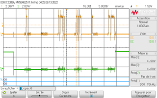
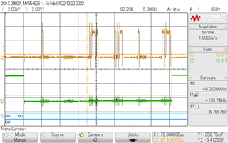
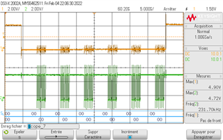
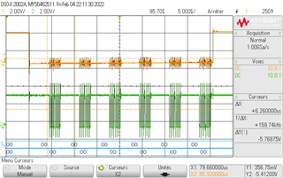
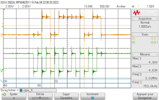
Moreover, when I look at the signals with a scope, they seem to be exactly the same. I can't understand where the problem comes from.
Here is the code :
SPI INITIALIZATION :
P6->OUT &= ~BIT3;
P6->DIR |= BIT3; // Set P1.0 LED
P6OUT = BIT3;
P6->OUT &= ~BIT4;
P6->DIR |= BIT4; // Set P1.0 LED
P6OUT = BIT4;
/* P2->OUT &= ~BIT1;
P2->DIR |= BIT1; // Set P1.0 LED
P2OUT = BIT1;
P2->OUT &= ~BIT0;
P2->DIR |= BIT0; // Set P1.0 LED
P2OUT = BIT0;*/
P6->SEL0 |= BIT3 | BIT4; // Set P1.5, P1.6, and P1.7 as
// SPI pins functionality
UCB1CTLW0 |= UCSWRST; // Put eUSCI state machine in reset
UCB1CTLW0 = UCSWRST | // Remain eUSCI state machine in reset
UCMST | // Set as SPI master
UCSYNC | // Set as synchronous mode
UCCKPL | // Set clock polarity high
UCMSB; // MSB first
UCB1CTLW0 |= UCSSEL__SMCLK; // ACLK
UCB1BRW = 0x01; // /2,fBitClock = fBRCLK/(UCBRx+1).
UCB1CTLW0 &= ~UCSWRST;// Initialize USCI state machine
And here is the code for the programming of the DDS :
int main(void)
{
WDTCTL = WDTPW | WDTHOLD; // Stop watchdog timer
// Terminate all remaining pins on the device
P2DIR |= 0xFF; P2OUT = 0;
P3DIR |= 0xFF; P3OUT = 0;
P4DIR |= 0xFF; P4OUT = 0;
P5DIR |= 0xFF; P5OUT = 0;
P6DIR |= 0xFF; P6OUT = 0;
P7DIR |= 0xFF; P7OUT = 0;
P8DIR |= 0xFF; P8OUT = 0;
P9DIR |= 0xFF; P9OUT = 0;
P10DIR |= 0xFF; P10OUT = 0;
/*** Fonctions d'initialisation ***/
initialisation_SPI();
/*** Fin des fonctions d'initalisation ***/
/*** Autorisation des interruptions ***/
__enable_interrupt();
NVIC->ISER[0] = 1 << ((EUSCIB1_IRQn) & 31);
/*** Fin de l'autorisation des interruptions ***/
while(1)
{
EUSCI_B1->IFG |= EUSCI_B_IFG_TXIFG;// Clear TXIFG flag
EUSCI_B1->IE |= EUSCI_B_IE_TXIE; // Enable TX interrupt
}
}
int _system_pre_init( void )
{
WDTCTL = WDTPW | WDTHOLD;
return 1;
}
// SPI interrupt service routine
void eUSCIB1IsrHandler(void)
{
if (UCB1IFG & UCTXIFG)
{
while(!(UCB1IFG & UCTXIFG));
P9OUT &= ~BIT3;
EUSCI_B1->TXBUF = 0x20; // Transmit characters
while(!(UCB1IFG & UCTXIFG));
EUSCI_B1->TXBUF = 0x00; // Transmit characters
while(!(UCB1IFG & UCTXIFG));
EUSCI_B1->TXBUF = 0x5D; // Transmit characters
while(!(UCB1IFG & UCTXIFG));
EUSCI_B1->TXBUF = 0x2B; // Transmit characters
while(!(UCB1IFG & UCTXIFG));
EUSCI_B1->TXBUF = 0x40; // Transmit characters
while(!(UCB1IFG & UCTXIFG));
EUSCI_B1->TXBUF = 0x6F; // Transmit characters
P9OUT |= BIT3;
UCB1IFG &=~ UCTXIFG;
G_uint8Fin_comm_adcFlag = 1 ;
}
}
Do you have any idea?
Thank you in advance,