This thread has been locked.

If you have a related question, please click the "Ask a related question" button in the top right corner. The newly created question will be automatically linked to this question.

[FAQ] Recover LaunchPad debugger ez-FET: MSP-EXP430F5529LP: No USB FET was found

Part Number: MSP-EXP430F5529LP
Other Parts Discussed in Thread: MSP430F5529, UNIFLASH, ENERGIA, MSP-FET, MSP-FLASHER, MSP430F5528

Hi everybody,

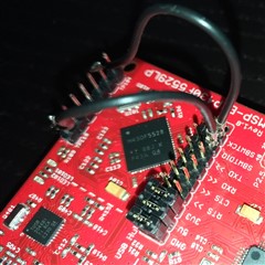
I have a new MSP-EXP430F5529LP board, but I can't get it to work.

Connecting the EVM to the PC via USB, I should see 2 new COM ports appear in the devices tree:
- MSP Application UART1
- MSP Debug Interface

Actually, after enumeration, I don't see these two ports, but only 4 new HID elements (all with VID=2047 and PID=0200):
- n.2 "HID-compliant vendor-defined device"
- n.2 "USB Input Device"

The result is this:
- both LEDs connected to the eZ-FET emulator on the board remain off
- both LEDs connected to the MSP430F5529 remain off
- all the tools that I tried like CCS, Energia and UniFlash fail to connect to the emulator reporting the error "Error initializing emulator: No USB FET was found"

I initially followed the "SLAU533D - MSP430F5529 LaunchPad Tm Development Kit" document and then I searched for more information on this forum, but without success so far.
I also downloaded and installed the low-level USB drivers (“ti_msp430driver_setup_1.0.1.2-windows”).

The PC used for these tests runs on Windows 10, I've done some tests also on Windows XP and Windows 7, but I don't get any improvement.

It would be great if you could give me some advice, thanks in advance.

Kind regards,
Marco

  • Hello Marco,

    It sounds to me like the FW for the EZ-FET (debugger side) is not on the board somehow. Do you have the ability to program an MSP430 outside this board? (Another LP or MSP-FET), if so can you follow the actions in this thread?  https://e2e.ti.com/support/microcontrollers/msp-low-power-microcontrollers-group/msp430/f/msp-low-power-microcontroller-forum/824521/msp-exp430f5529lp-no-fet-device-found 

  • I like 5529LP because of possibility to have two eZ-FET's (one original on 5528 master and another on 5529 target device) connected to PC by one USB cable.

    Run on Win (HID BSL) Firmware Update Example with LP connected to PC. If everything related to LP hardware is OK, at least target 5529 device should enter (hold BSL button during power up or reset) to BSL mode. If target device is working OK and you are able to upload any example by BSL GUI, than I can attach here eZ-FET firmware (last open source version) that will not touch device BSL and info segments (like original one). And than from target device (5529) used as FET master you can upload original ez-FET firmware on real master (5528), and update it later with MSP-Flasher to last ddl version.

  • Hi Jace, unfortunately I don't have another board, but I will try the suggestion given by Zrno Soli.

  • Hi Zrno, thank you for your information, I wil try to implement what you suggested.

  • Hi Zrno,

    I added a pushbutton and a 100 Ohm restistor between eZ-FET (5528) PUR and +3.3V so now I'm able to put both the 5528 and 5529 in BSL mode.

    Using the application "Python_Firmware_UpgraderGUI.exe" I was able to correctly load each one with a simple blink example (green LED for 5528 and red LED for 5529).

    So I think that now I could load on the 5529 the right eZ-FET firmware, is it possible to have this binary directly in TI-TXT format?

    Regards,

    Marco

  • Hey Marco,

    It is good that you can use BSL for the devices on board. Make sure to target the MSP430F5528 that is on the debugger portion f the board and download the ez-FETLite FW located here: https://software-dl.ti.com/msp430/msp430_public_sw/mcu/msp430/MSP430_ezFETLite/latest/index_FDS.html 

    This is an older version of FW, so after download and reconnect, CCS may ask to update it. Please do so. 

  • Hi Jace,

    thank you for your reply.

    I was able to load ez-FETLite on the 5528, now I can see both "MSP Application UART1" and "MSP Debug Interface", but when I try to load a new FW to 5529 I have this error in CCS: "MSP430: Error initializing emulator: Could not set device Vcc".

    I can't find a way to update ez-FETLite in CCS (I used "EZFET_LITE_Rev1_1_FW_3_3_0_6.txt" version and CCS 11 doesn't seem to notice that it has to be updated).

  • Don't know about python, but win GUI version in C will load new HID BSL version to RAM and execute it from there, so factory BSL in device flash should be able for update also.

    TI eZ-FET firmware use BSL and Info A flash segments that are locked by default, and they must be unlocked by BSL first. Here is example for SBW / JTAG (not BSL).

    ssihla.wordpress.com/.../

  • Hi Zrno,

    at this point I'm able to load new FW using BSL and an application on the PC, the problem in my opinion is this: where can I find the current FW version for ez-FETLite to be loaded into the 5528?

    I'm also investigating on this error in CCS 11: "MSP430: Error initializing emulator: Could not set device Vcc".

    Regards,

    Marco

  • Check the link from my last post. This reported error is related to missing part of downloaded firmware. BSL and Info A flash segments are locked by default, and part of firmware will not be downloaded there. Because of these (even device is enumerated as composite CDC, one for FET and another for UART bridge) there is reported error in CCS.

    I need some time for prepare my setup, and than I will attach here firmware that don't use BSL and Info A flash segments. Than you can download this by BSL to target 5529 target device and than use target device as master to download full standard TI firmware to 5528 target by SBW connected over unpopulated header near 5528. By MSPFlasher as on link from my last post.

  • 1. Remove all jumpers between master and target devices except GND, 5V and 3V3.

    2. Using MSP430_USB_Firmware_Upgrade_Example-1.3.1.1 update Blink LED example to both (5528 master and 5529 target) devices. If everything is OK, on board  bottom red LED (P1.0 LED1) should blink.

    3. Enter to HID BSL mode with target device (5529) by pressing together RESET and BSL button and release RESET first. Blinking should stop. Using MSP430_USB_Firmware_Upgrade_Example-1.3.1.1 update firmware of target device (5529) with attached "eZ-FET_custom.txt" file. Now you have fully working eZ-FET Lite on target device (5529) that will be used with MSP430Flasher for LP recovery.

    4 Made SBW connection between 5529 and 5528, P4.2 SBW_RST -> TP110, P4.3 SBW_TST -> TP105. Use MSP430Flasher to check connection, for exmple...

    MSP430Flasher -i COM9 -j slow -e ERASE_ALL

    If MSP430Flasher prompt about update don't do it, because custom version don't support this.

    5. If MSP430Flasher working fine with custom firmware on 5529 download TI eZ-FET firmware on 5528. Binary firmware (EZFET_LITE_Rev1_1_FW_3_3_0_6.txt) can be found in "eZ-FET_lite_Release_Package_rev_1_10_20130712.zip" that can be downloaded here...

    https://software-dl.ti.com/msp430/msp430_public_sw/mcu/msp430/MSP430_ezFETLite/latest/index_FDS.html

    This is MSP430Flasher line used for this (Info A segment and BSL must be unlocked) ...

    MSP430Flasher -j slow -u -b -e ERASE_ALL -w EZFET_LITE_Rev1_1_FW_3_3_0_6.txt -v -z [VCC]

    After 5528 is restarted and enumerated as eZ-FET, MSP430Flasher can be used to updated 5528 firmware version to the last one by itself (without using 5529).

  • Hi Zrno,

    I implemented steps 1 to 4, but when I run "MSP430Flasher -i COM7 -j slow -e ERASE_ALL" I get this:

    * Evaluating triggers...done
    * Checking for available FET debuggers:
    * Found USB FET @ COM7 <- Selected
    * Initializing interface @ COM7...done
    * Setting FET speed...done
    * Checking firmware compatibility:
    * FET firmware is up to date.
    * Reading FW version...done
    * Setting VCC to 3000 mV...done
    * Accessing device...
    # Exit: 16
    # ERROR: Unknown device
    * Powering down...done
    * Disconnecting from device...done

    With a scope I see that TP110 is always '1' and TP105 is always '0' during this procedure.

  • You must connect TP to P4.2 and P4.3 of 5529, on target device 5529 board part, left and right headers (without black plastic from top side). With this connection on your picture, only TEST pin of both, 5528 and 5529 is connected together, and REST too.

  • Hi Zrno,

    ok I set the right connections, this is the result:

    MSP430Flasher -j slow -u -b -e ERASE_ALL -w EZFET_LITE_Rev1_1_FW_3_3_0_6.txt -v -z [VCC]

    * -----/|-------------------------------------------------------------------- *
    *     / |__                                                                   *
    *    /_   /   MSP Flasher v1.3.20                                             *
    *      | /                                                                    *
    * -----|/-------------------------------------------------------------------- *
    *
    * Evaluating triggers...done
    * Checking for available FET debuggers:
    * Found USB FET @ COM7 <- Selected
    * Initializing interface @ COM7...done
    * Setting FET speed...done
    * Checking firmware compatibility:
    * FET firmware is up to date.
    * Reading FW version...
    * Debugger does not support target voltages other than 3000 mV!
    * Setting VCC to 3000 mV...done
    * Accessing device...done
    * Reading device information...done
    * Unlocking BSL memory...done
    * Unlocking Info Memory A...done
    * Loading file into device...done
    * Verifying memory (EZFET_LITE_Rev1_1_FW_3_3_0_6.txt)...done
    *
    * ----------------------------------------------------------------------------
    * Arguments   : -j SLOW -u -b -e ERASE_ALL -w EZFET_LITE_Rev1_1_FW_3_3_0_6.txt -v -z [VCC]
    * ----------------------------------------------------------------------------
    * Driver      : loaded
    * Dll Version : 31400000
    * FwVersion   : 31200000
    * Interface   : TIUSB
    * HwVersion   : E 3.0
    * JTAG Mode   : AUTO
    * Device      : MSP430F5528
    * EEM         : Level 7, ClockCntrl 2
    * Erase Mode  : ERASE_ALL
    * Prog.File   : EZFET_LITE_Rev1_1_FW_3_3_0_6.txt
    * Verified    : TRUE
    * BSL Unlock  : TRUE
    * InfoA Access: TRUE
    * VCC ON      : 3000 mV
    * ----------------------------------------------------------------------------
    * Starting target code execution...done
    * Disconnecting from device...done
    *
    * ----------------------------------------------------------------------------
    * Driver      : closed (No error)
    * ----------------------------------------------------------------------------

    This is what I did next:

    - I restarted the board and loaded a Blink LED example on the 5529 to remove the target eZ-FET

    - restarted the board again

    - I tried to debug the example with CCS, but I still get "Could not set device Vcc".

  • Try to erase target 5529 device with MSP430Flasher using 5528 as master (remove recovery wires, and put back SBW jumpers). MSP430Flasher will ask for eZ-FET firmware update, and do it. Post log here.

    As I can see from MSP430Fasher log, loading TI eZ-FET firmware to 5528 was without issues.

    EDIT: sorry, my mistake.

    BSL is missing in "EZFET_LITE_Rev1_1_FW_3_3_0_6.txt". Do it again, from point 1, but use attached file (TI eZ-FET with included BSL) for 5528.

    EZFET_LITE_Rev1_1_FW_3_3_0_6_and_BSL_1_1.zip

  • Hi Zrno, you really did a great job! Now the board is working correctly!!

    Many thanks.

    Regards,

    Marco

**Attention** This is a public forum