This thread has been locked.

If you have a related question, please click the "Ask a related question" button in the top right corner. The newly created question will be automatically linked to this question.

MSP430FR6043: Water Flow Meter - Board connection in source code

Part Number: MSP430FR6043
Other Parts Discussed in Thread: EVM430-FR6043

Hi,

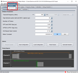
I'm working on the Water Flow Measurement project. By deafult, the Design Center GUI is used to communicate with the board and do the measurements. Because of my project requirements, I should not use the GUI and use only the code loaded in the board, to automate the process. I already found where volume flow rate and other parameters are set and used. Is there any way to modify the code in order to do what the Connect button GUI does?

Thanks in advance,

Alberto

  • There are two separate code repositories you can use for flow meters. One requires the GUI as you have implemented, and the other is a standalone meter that can drive an LCD or be modified to communicate over UART for example. Both are based off of the same software library.

    If you have the USS-SWLIB-WATER driver installed, you will find the standalone projects in its install directory, in USS\examples\USSSWLib_template_example. Import the correct processor project into CCS and start from there.

    I'd recommend using the standalone from the example template project; the version interfacing with the GUI is not necessarily optimized for a water meter application, just evaluation of the TI Ultrasonic library.

  • Hi Seth,

    Thanks for the information. I runned the project code and tried to configure transmit frequency and ADC gain as I configured in the GUI but I'm getting zero value in Volume Flow Rate for instance. Is there any example or guide to help me configure these parameters correctly?

    Regards,

    Alberto

  • The best way to get the initial settings correct is to setup as you did with the GUI, press the "Generate Headers" button, and place those headers in the correct folder for the "USSSWLib_template_example"; the files will be named the same. Then recompile the example project and run it. The measured values should then be very close to what was displayed in the GUI.

    USS GUI Generate Headers

    More detailed information can be found in the Library User Guide as well as the Library Architecture document. It took me a while to start to figure this out too, because the documents are spread out around the website. There's also the Ultrasonic Water Meter Academy page which details getting your meter all setup using the GUI so everything will be ready when you "Generate Headers".

  • I followed your paths but I'm not getting the same results as in the GUI. Moreover, I'm obtaining negative volume flow rate values (around -5 L/h) whereas the GUI values are still correct.

    I attach the "main.c" and "USS_userConfig.h" files just in case there could be an error, but as it's self generated I don't think there can be.

    74485.main.c
    /* --COPYRIGHT--,BSD
     * Copyright (C) 2019 Texas Instruments Incorporated - http://www.ti.com/
     *
     *
     *  Redistribution and use in source and binary forms, with or without
     *  modification, are permitted provided that the following conditions
     *  are met:
     *
     *    Redistributions of source code must retain the above copyright
     *    notice, this list of conditions and the following disclaimer.
     *
     *    Redistributions in binary form must reproduce the above copyright
     *    notice, this list of conditions and the following disclaimer in the
     *    documentation and/or other materials provided with the
     *    distribution.
     *
     *    Neither the name of Texas Instruments Incorporated nor the names of
     *    its contributors may be used to endorse or promote products derived
     *    from this software without specific prior written permission.
     *
     *  THIS SOFTWARE IS PROVIDED BY THE COPYRIGHT HOLDERS AND CONTRIBUTORS
     *  "AS IS" AND ANY EXPRESS OR IMPLIED WARRANTIES, INCLUDING, BUT NOT
     *  LIMITED TO, THE IMPLIED WARRANTIES OF MERCHANTABILITY AND FITNESS FOR
     *  A PARTICULAR PURPOSE ARE DISCLAIMED. IN NO EVENT SHALL THE COPYRIGHT
     *  OWNER OR CONTRIBUTORS BE LIABLE FOR ANY DIRECT, INDIRECT, INCIDENTAL,
     *  SPECIAL, EXEMPLARY, OR CONSEQUENTIAL DAMAGES (INCLUDING, BUT NOT
     *  LIMITED TO, PROCUREMENT OF SUBSTITUTE GOODS OR SERVICES; LOSS OF USE,
     *  DATA, OR PROFITS; OR BUSINESS INTERRUPTION) HOWEVER CAUSED AND ON ANY
     *  THEORY OF LIABILITY, WHETHER IN CONTRACT, STRICT LIABILITY, OR TORT
     *  (INCLUDING NEGLIGENCE OR OTHERWISE) ARISING IN ANY WAY OUT OF THE USE
     *  OF THIS SOFTWARE, EVEN IF ADVISED OF THE POSSIBILITY OF SUCH DAMAGE.
     *
     * --/COPYRIGHT--*/
    #include <msp430.h>
    #include "main.h"
    #include <stdio.h>
    
    float volt;
    float resistance;
    float pressure;
    float temperature;
    
    USS_Algorithms_Results algorithms_Results;
    
    static void checkCode(USS_message_code code, USS_message_code expectedCode);
    static void handlePllUnlockEvent(void);
    static void disableApplicationInterrupts(void);
    static void enableApplicationInterrupts(void);
    
    #if APPLICATION_ENABLE_UART_DEBUG
    static void uartTxByte(char string);
    static void uartTxHexByte(uint8_t Data);
    static uint8_t nibbleToHex(uint8_t nibble);
    static void uartTxUSSResult(uint8_t delimiter, float *data);
    #endif
    
    int main(void)
    {
    #if (APPLICATION_ENABLE_CHANNEL_SWAP == true)
        uint16_t appSwapInterval = APPLICATION_CHANNEL_SWAP_INTERVAL;
    #endif
    
    #if (APPLICATION_ENABLE_ABSTOF_DTOF_OFFSET_CALIBRATION == true)
        USS_dTof_absTof_offset_results abstoFDtofTestResults;
        USS_dTof_absTof_offset_test_config abstoFDtofTestConfig =
        {
             .numOfTestIterations        = APPLICATION_ABSTOF_DTOF_OFFSET_UPDATE_INTERVAL,
             .isUseLPMCapture            = APPLICATION_ABSTOF_DTOF_OFFSET_LPM_CAPTURE,
             .isCalculateUpsAbsTofOffset = APPLICATION_ABSTOF_DTOF_OFFSET_CALC_UPS_ABSTOF,
             .isCalculateDnsAbsTofOffset = APPLICATION_ABSTOF_DTOF_OFFSET_CALC_DNS_ABSTOF,
             .isCalculateDToFOffset      = APPLICATION_ABSTOF_DTOF_OFFSET_CALC_DTOF,
        };
    #endif
    
        volatile USS_message_code code;
        USS_Algorithms_Results algResults;
        USS_calibration_hspll_results testResults;
    
    
        // Register PLL unlock event
        USS_registerHSPLLInterruptCallback(USS_HSPLL_Interrupt_PLLUNLOCK,
                                           &handlePllUnlockEvent);
    
        code = USS_configureUltrasonicMeasurement(&gUssSWConfig);
        checkCode(code, USS_message_code_no_error);
    
    #if((USS_ALG_ABS_TOF_COMPUTATION_MODE == USS_ALG_ABS_TOF_COMPUTATION_MODE_LOBE_WIDE) || \
        (USS_ALG_ABS_TOF_COMPUTATION_MODE == USS_ALG_ABS_TOF_COMPUTATION_MODE_HILBERT_WIDE))
        // Reference binary pattern are only needed by
        // USS_Alg_AbsToF_Calculation_Option_lobeWide and
        // USS_Alg_AbsToF_Calculation_Option_hilbertWide AbsToF computation options
        if((USS_Alg_AbsToF_Calculation_Option_lobeWide ==
                gUssSWConfig.algorithmsConfig->absToFOption)
           || (USS_Alg_AbsToF_Calculation_Option_hilbertWide ==
                   gUssSWConfig.algorithmsConfig->absToFOption))
        {
    #if defined(__MSP430_HAS_SAPH_A__)
            if(USS_measurement_pulse_generation_mode_multi_tone ==
                    gUssSWConfig.measurementConfig->pulseConfig->pulseGenMode)
            {
                code = USS_generateMultiToneBinaryPattern(&gUssSWConfig);
                checkCode(code, USS_message_code_no_error);
            }
    #endif
            if(USS_measurement_pulse_generation_mode_multi_tone !=
                    gUssSWConfig.measurementConfig->pulseConfig->pulseGenMode)
            {
                code = USS_generateMonoDualToneBinaryPattern(&gUssSWConfig);
                checkCode(code, USS_message_code_no_error);
            }
        }
    
    #if (APPLICATION_ENABLE_BINARY_PATTERN_SIZE_SCALING == true)
        gUssSWConfig.algorithmsConfig->binaryPatternLength =
                (gUssSWConfig.captureConfig->sampleSize / APPLICATION_BINARY_PATTERN_SCALE_FACTOR);
    #endif
    
    #endif
    
    
        // Application must ensure no application level interrupts occur while
        // verifying HSPLL Frequency
        disableApplicationInterrupts();
    
        code = USS_verifyHSPLLFrequency(&gUssSWConfig, &testResults);
    
        // Application can re-enable interrupts after HSPLL verification
        enableApplicationInterrupts();
    
        checkCode(code, USS_message_code_no_error);
    
        gUssSWConfig.algorithmsConfig->clockRelativeError = _IQ27div((int32_t)(testResults.actualTestCount -
                testResults.expectedResult),testResults.expectedResult);
    
        code = USS_initAlgorithms(&gUssSWConfig);
        checkCode(code, USS_message_code_no_error);
    
    #if (APPLICATION_ENABLE_SIGNAL_GAIN_CALIBRATION == true)
        code = USS_calibrateSignalGain(&gUssSWConfig);
        checkCode(code, USS_message_code_Signal_Gain_Calibration_successful);
    #endif
    
    #if (APPLICATION_ENABLE_ABSTOF_DTOF_OFFSET_CALIBRATION == true)
        code = USS_calculateOffsets(&gUssSWConfig, &abstoFDtofTestResults,
                                    &abstoFDtofTestConfig);
        checkCode(code, USS_message_code_no_error);
    
        code = USS_updateAdditionalCaptureDelay(&gUssSWConfig,
              ((abstoFDtofTestResults.upsAbsToFOffset + abstoFDtofTestResults.dnsAbsToFOffset) /2.0f) -
              APPLICATION_ABSTOF_REFERENCE);
        checkCode(code, USS_message_code_no_error);
    
        code = USS_updateDtoFOffset(&gUssSWConfig, (-1.0f *abstoFDtofTestResults.dToFOffset));
        checkCode(code, USS_message_code_no_error);
    
    #endif
    
        // Set the background timer period to 1 second
        USS_configAppTimerPeriod(&gUssSWConfig, gUssSWConfig.systemConfig->measurementPeriod);
        /************* ADC CONFIGURATION *******************/
        WDTCTL = WDTPW | WDTHOLD;               // Stop WDT
    
        // GPIO Setup
        P1SEL1 |= BIT0;                         // Configure P.1.0 for ADC
        P1SEL0 |= BIT0;
        P1SEL1 |= BIT1;                         // Configure P1.1 for ADC
        P1SEL0 |= BIT1;
    
        // Disable the GPIO power-on default high-impedance mode to activate
        // previously configured port settings
        PM5CTL0 &= ~LOCKLPM5;
                                                                                // Internal Reference ON
        // Configure ADC12
        ADC12CTL0 = ADC12SHT0_2 | ADC12ON;
        ADC12CTL1 = ADC12SHP + ADC12CONSEQ_1;                   // ADCCLK = MODOSC; sampling timer
        ADC12CTL2 |= ADC12RES_2;                // 12-bit conversion results
        ADC12IER0 |= ADC12IE0;                  // Enable ADC conv complete interrupt
    
        ADC12MCTL0 |= ADC12INCH_0;              // A0 ADC input select; Vref=AVCC // PRESSURE
        ADC12MCTL1 |= ADC12INCH_1+ADC12EOS;              // A1 ADC input select; Vref=AVCC // TEMPERATURE
        /**************************************************/
    
        /************* UART RX CONFIGURATION ********************/
        //UCA1IE |= UCRXIE;                       // Enable USCI_A1 RX interrupt. RXD J1
    
        while(1)
        {
            code = USS_startLowPowerUltrasonicCapture(&gUssSWConfig);
            checkCode(code, USS_message_code_no_error);
    
            code = USS_runAlgorithms(&gUssSWConfig,&algResults);
            checkCode(code, USS_message_code_valid_results);
    
    #if (APPLICATION_ENABLE_CHANNEL_SWAP == true)
            if(appSwapInterval == 0)
            {
                code = USS_swapCaptureChannels(&gUssSWConfig);
                code = USS_swapAlgorithmsCaptureBuffers(&gUssSWConfig);
    
                appSwapInterval = APPLICATION_CHANNEL_SWAP_INTERVAL;
            }else{
                appSwapInterval--;
            }
    #endif
    
    #if APPLICATION_ENABLE_UART_DEBUG
            uartTxUSSResult(APPLICATION_UART_ABSTOF_UPS_DELIM,&algResults.totalTOF_UPS);
            uartTxUSSResult(APPLICATION_UART_ABSTOF_DNS_DELIM,&algResults.totalTOF_DNS);
            uartTxUSSResult(APPLICATION_UART_DTOF_DELIM,&algResults.deltaTOF);
            puts("UART");
            uartTxUSSResult(APPLICATION_UART_VFR_DELIM,&algResults.volumeFlowRate);
            ADC12CTL0 |= ADC12ENC | ADC12SC;    // Sampling and conversion start
            __bis_SR_register(LPM0_bits + GIE); // LPM0, ADC10_ISR will force exit
            __no_operation();
    #endif
            if(algResults.volumeFlowRate<0)// && algResults.delatTOF>-10)
                puts("Caudal");
            // Wait for timer to elapse
    
            USS_waitForAppTimerElapse(&gUssSWConfig,USS_low_power_mode_option_low_power_mode_3);
    
        }
    }
    
    #if APPLICATION_ENABLE_UART_DEBUG
    
    void uartTxByte(char string)
    {
        while(!(UCA1IFG & UCTXIFG));
        UCA1TXBUF = string;
    }
    
    void uartTxHexByte(uint8_t Data)
    {
        uartTxByte(nibbleToHex(Data >> 4));
        uartTxByte(nibbleToHex(Data & 0x0F));
    }
    
    uint8_t nibbleToHex(uint8_t nibble)
    {
        uint8_t ret = nibble;
        if(nibble < 10)
        {
            ret += '0';
        }
        else
        {
            ret += 'A' - 10;
        }
    
        return(ret);
    }
    
    void uartTxUSSResult(uint8_t delimiter, float *data)
    {
        uint8_t *ptr;
    
        // Send delimiter
        uartTxByte(delimiter);
        // Send comma
        uartTxByte(',');
    
        ptr = (uint8_t *) data;
    
        // Send float values
        uartTxHexByte(ptr[3]);
        uartTxHexByte(ptr[2]);
        uartTxHexByte(ptr[1]);
        uartTxHexByte(ptr[0]);
    
        // Send new line return
        uartTxByte('\n');
        uartTxByte('\r');
    }
    #endif


    void handlePllUnlockEvent(void)
    {
        // If USS PLL unlock event is detected rest USS Module and reconfigure
        // measurement
        USS_resetUSSModule(&gUssSWConfig, true);
    }
    
    
    // This is a place holder for the application to disable interrupts which might
    // be triggered during HSPLL verification
    void disableApplicationInterrupts(void){
    
    }
    
    // This is a place holder for the application to enable interrupts once
    // HSPLL verification has completed
    void enableApplicationInterrupts(void){
    
    }
    
    void checkCode(USS_message_code code, USS_message_code expectedCode)
    {
        if(code != expectedCode)
        {
            // Trap code
            while(1);
        }
    }
    
    // ADC interrupt service routine
    #if defined(__TI_COMPILER_VERSION__) || defined(__IAR_SYSTEMS_ICC__)
    #pragma vector = ADC12_B_VECTOR
    __interrupt void ADC12_ISR(void)
    #elif defined(__GNUC__)
    void __attribute__ ((interrupt(ADC12_B_VECTOR))) ADC12_ISR (void)
    #else
    #error Compiler not supported!
    #endif
    {
        switch (__even_in_range(ADC12IV, ADC12IV__ADC12RDYIFG))
        {
            case ADC12IV__NONE:        break;   // Vector  0:  No interrupt
            case ADC12IV__ADC12OVIFG:  break;   // Vector  2:  ADC12MEMx Overflow
            case ADC12IV__ADC12TOVIFG: break;   // Vector  4:  Conversion time overflow
            case ADC12IV__ADC12HIIFG:  break;   // Vector  6:  ADC12BHI
            case ADC12IV__ADC12LOIFG:  break;   // Vector  8:  ADC12BLO
            case ADC12IV__ADC12INIFG:  break;   // Vector 10:  ADC12BIN
            case ADC12IV__ADC12IFG0:            // Vector 12:  ADC12MEM0 Interrupt // PRESSURE
                puts("ADC");
                volt = ADC12MEM0*3.3/4095.0;
                pressure = 3*(volt*1.5-0.5);
                //printf("Presion (bar): %f\n",pressure);
                volt = ADC12MEM1*3.3/4095.0;
                resistance = 10000.0*volt/(3.3-volt); //Rref*Vt/(Vi-Vt)
                temperature = 3950.0/(log(resistance/10000.0)+(3950.0/298.0))-273.0;
                //printf("Temperatura: %f\n",temperature);
    
                __bic_SR_register_on_exit(LPM0_bits); // Exit active CPU
                break;                          // Clear CPUOFF bit from 0(SR)
            case ADC12IV__ADC12IFG1:   break;   // Vector 14:  ADC12MEM1 // TEMPERATURE
            case ADC12IV__ADC12IFG2:   break;   // Vector 16:  ADC12MEM2
            case ADC12IV__ADC12IFG3:   break;   // Vector 18:  ADC12MEM3
            case ADC12IV__ADC12IFG4:   break;   // Vector 20:  ADC12MEM4
            case ADC12IV__ADC12IFG5:   break;   // Vector 22:  ADC12MEM5
            case ADC12IV__ADC12IFG6:   break;   // Vector 24:  ADC12MEM6
            case ADC12IV__ADC12IFG7:   break;   // Vector 26:  ADC12MEM7
            case ADC12IV__ADC12IFG8:   break;   // Vector 28:  ADC12MEM8
            case ADC12IV__ADC12IFG9:   break;   // Vector 30:  ADC12MEM9
            case ADC12IV__ADC12IFG10:  break;   // Vector 32:  ADC12MEM10
            case ADC12IV__ADC12IFG11:  break;   // Vector 34:  ADC12MEM11
            case ADC12IV__ADC12IFG12:  break;   // Vector 36:  ADC12MEM12
            case ADC12IV__ADC12IFG13:  break;   // Vector 38:  ADC12MEM13
            case ADC12IV__ADC12IFG14:  break;   // Vector 40:  ADC12MEM14
            case ADC12IV__ADC12IFG15:  break;   // Vector 42:  ADC12MEM15
            case ADC12IV__ADC12IFG16:  break;   // Vector 44:  ADC12MEM16
            case ADC12IV__ADC12IFG17:  break;   // Vector 46:  ADC12MEM17
            case ADC12IV__ADC12IFG18:  break;   // Vector 48:  ADC12MEM18
            case ADC12IV__ADC12IFG19:  break;   // Vector 50:  ADC12MEM19
            case ADC12IV__ADC12IFG20:  break;   // Vector 52:  ADC12MEM20
            case ADC12IV__ADC12IFG21:  break;   // Vector 54:  ADC12MEM21
            case ADC12IV__ADC12IFG22:  break;   // Vector 56:  ADC12MEM22
            case ADC12IV__ADC12IFG23:  break;   // Vector 58:  ADC12MEM23
            case ADC12IV__ADC12IFG24:  break;   // Vector 60:  ADC12MEM24
            case ADC12IV__ADC12IFG25:  break;   // Vector 62:  ADC12MEM25
            case ADC12IV__ADC12IFG26:  break;   // Vector 64:  ADC12MEM26
            case ADC12IV__ADC12IFG27:  break;   // Vector 66:  ADC12MEM27
            case ADC12IV__ADC12IFG28:  break;   // Vector 68:  ADC12MEM28
            case ADC12IV__ADC12IFG29:  break;   // Vector 70:  ADC12MEM29
            case ADC12IV__ADC12IFG30:  break;   // Vector 72:  ADC12MEM30
            case ADC12IV__ADC12IFG31:  break;   // Vector 74:  ADC12MEM31
            case ADC12IV__ADC12RDYIFG: break;   // Vector 76:  ADC12RDY
            default: break;
        }
    }
    /*********************************************************************/
    /************************ UART INTERRUPTION ***********************/
    #if defined(__TI_COMPILER_VERSION__) || defined(__IAR_SYSTEMS_ICC__)
    #pragma vector=EUSCI_A1_VECTOR
    __interrupt void USCI_A1_ISR(void)
    #elif defined(__GNUC__)
    void __attribute__ ((interrupt(EUSCI_A1_VECTOR))) USCI_A_ISR (void)
    #else
    #error Compiler not supported!
    #endif
    {
        switch(__even_in_range(UCA1IV, USCI_UART_UCTXCPTIFG))
        {
            case USCI_NONE: break;
            case USCI_UART_UCRXIFG:
                puts("Interrupcion");
                /*RXData = UCA1RXBUF;             // Read buffer
                if(RXData != TXData)            // Check value
                {
                    //P1OUT |= BIT5;              // If incorrect turn on P1.0
                    puts("Dato incorrecto");
                }
                else{
                    puts("Dato correcto");
                }
    
                TXData++;                       // increment data byte*/
                __bic_SR_register_on_exit(LPM0_bits); // Exit LPM0 on reti
                break;
            case USCI_UART_UCTXIFG: break;
            case USCI_UART_UCSTTIFG: break;
            case USCI_UART_UCTXCPTIFG: break;
            default: break;
        }
    }
    /************************************************************************/
    
    0216.USS_userConfig.h

  • Are you using the EVM430-FR6043 or is this with a custom designed circuit board?

  • I'm using EVM430-FR6043. I only did the hardware modifications needed for water measurements, as guide suggests.

    I've deleted and created new project adding just the headers again. Now I'm not getting negative values, but almost zero ones.

  • In Project Properties -> Build -> MSP430 Compiler -> Predefined Symbols delete anything that looks like "__AFE_EXT_3v3__" or "__AFE_EXT_5v0__".

    If those are in that list, some of the register settings get set differently in the USS_Lib_HAL.c and ussSwLibMeasurement.c which would make your measurements incorrect.

  • I removed "__AFE_EXT_3v3__" but I'm getting the same wrong measurements.

  • Hi Seth,

    Thanks for your help. I solved the problem by another way. I used Water Demo project but I removed HMI function and now it works. If someone has the same issue, see this thread for further information.

**Attention** This is a public forum