This thread has been locked.

If you have a related question, please click the "Ask a related question" button in the top right corner. The newly created question will be automatically linked to this question.

MSP430FR60471: Applying bandpass filter on Ultrasonic Signal

Part Number: MSP430FR60471
Other Parts Discussed in Thread: MSP430FR6047

Hi Team,

We are trying to apply band pass filter on the ultrasonic signals. While testing at Zero Flow, the ADC Capture looks like this (when filter is enabled using: USS_ALG_FILT_IS_FILTER_ENABLED macro). 

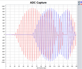
When the filter is not used, we see exactly overlapping signals from the two channels (at Zero Flow). What is introducing this offset between the signals? How can it be removed?

Regards,

Kamlesh

  • Hi,

    It is caused by when using the filter function, the size of the data after filtered is (original size + filter size). And the data sent to the GUI still keeps the original format. It should only be a display issue. It is not going to influence the dTOF and absTOF result. Can you share a screenshot of the waveform page when you enable the filter?

    Best regards,

    Cash Hao

  • Hi,

    The above waveform is after enabling filter. I agree that the data length increases, but this should increase for both data arrays, right?

    Regards,

    Kamlesh

  • Hi,

    Yes, but the the UPS and DNS data are all saved in one array. 

    The capture you send is from the ADC capture page not the waveform page. Could you send a screenshot on the waveform page when you apply the filter?

    Best regards,

    Cash Hao

  • Hi,

    Below figure is when the filter was not used (at Zero Flow):


    Below figure: when filter is enabled (at Zero Flow). I understand, there is not much difference in both cases. Also, One more information, I have changed the order of the lines:

                    code = USS_runAlgorithmsFixedPoint(&gUssSWConfig,&algResFixed);
                    HMI_PostMeasurement_Update();
                    
                    // earlier the order was:
                    HMI_PostMeasurement_Update();
                    code = USS_runAlgorithmsFixedPoint(&gUssSWConfig,&algResFixed);
                    
                    
                    // This was done to show the filtered data on GUI

    Regards,

    Kamlesh

  • Doesn't the below address the change in array size due to filter enabling? We just want to be sure that enabling filter is not messing up with other parameters.

    void CommandHandler_transmitCaptures(Packet_t *txPacket)
    {
    // Calculate number of packets that will need to be sent
    // Each ADC capture packet can hold up to 27 captures
    uint16_t updnsCaptureSize = gUssSWConfig.captureConfig->sampleSize;
    uint8_t numOfPcks = (uint8_t)(updnsCaptureSize/ COMMAND_HANDLER_UPS_DNS_CAP_MAX_CAP_SIZE);
    int8_t finalPckLength = (uint8_t)(updnsCaptureSize % COMMAND_HANDLER_UPS_DNS_CAP_MAX_CAP_SIZE);
    // Calculate number of bytes in each capture
    uint8_t* pUPSCap = (uint8_t*)(USS_getUPSPtr(&gUssSWConfig));
    uint8_t* pDNSCap = (uint8_t*)(USS_getDNSPtr(&gUssSWConfig));
    
    if( finalPckLength > 0 )
    {
    numOfPcks++;
    }
    else
    {
    finalPckLength = COMMAND_HANDLER_UPS_DNS_CAP_MAX_CAP_SIZE;
    }
    .....

    It seems like the pUPSCap and pDNSCap are not able to address this. Can we do something about this?

    Regards,

    Kamlesh

  • Hi,

    Enable the filter function is not going to mess up with other parameters. 

    I think the overlap signals on the ADC capture might cause by the USS GUI not the MCU. 

    Best regards,

    Cash Hao

  • Okay. And could you please point to me resources having information on power consumption in MSP430Fr6047, when the filter and other processes are turned on ?

    Regards,

    Kamlesh

  • Well, we do not have that information. We only have the current consumption data with the basic measurement functions in this APP note chapter 3.2.2.5. https://www.ti.com/lit/ug/tidudn0/tidudn0.pdf

    Best regards,

    Cash Hao

  • Thank you for sharing this info. The section has a line : "For brevity, it does not include configuration parameters that have no impact on current consumption" and as the filter enabling or disabling is not mentioned in the parameters included in the calculation. Can we infer from here that filter doesn't have much impact on power consumption even in long term?

    Regards,

    Kamlesh

  • No, we can not get that conclusion from that context. It is recommended to test the current consumption with and without the filter function to get the exact data.

    Best regards,

    Cash Hao

  • Okay. Thanks for this info.

    Regards,

    Kamlesh

**Attention** This is a public forum