This thread has been locked.

If you have a related question, please click the "Ask a related question" button in the top right corner. The newly created question will be automatically linked to this question.

MSP430FG6426: Code stuck at __delay_cycles during debug mode

Part Number: MSP430FG6426

Dear Team,

A strange problem suddenly arised which we have no clue about, could you please help here ?

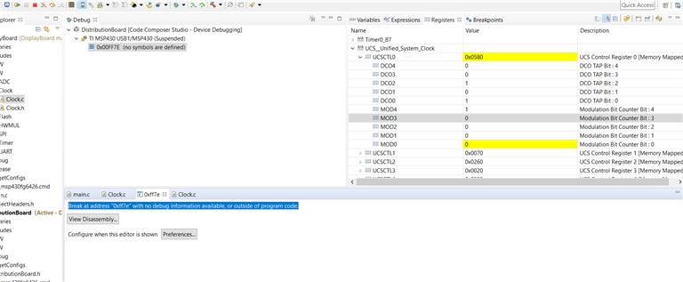
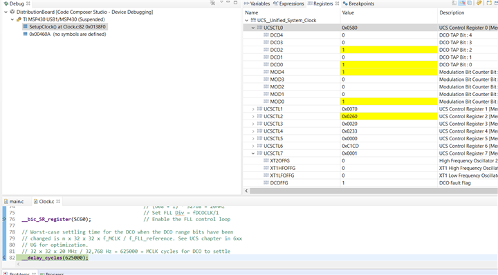
When we flash our software in debug session the code runs well until the first hit of __delay_cycles and does not proceed further from here. Whenever i pause the execution the break point stays here and does not proceed..

But the same code runs well and my software functions normal with the same software without the debug session (just stopped the debug sessions and hit the reset button on the board). the same software in release mode is running in some of our units without any issues.

I tried to recreate a fresh project and import the sources and the debug session works for the very first instance, and the problem comes up again from the second debug session onwards. Not sure where things are going wrong and need your support here.

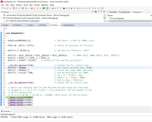
I have placed my code here for reference

https://drive.google.com/file/d/1FmchPJjhVtBZjGTt-U79aiARngcFVcnF/view?usp=sharing

Thanks

Surya

  • Hi Surya,

    Is DCOFFG set in your application during debug? Do you see UCSCTL0 register updating? DCORSEL_7 should technically work as the max for a tap of 0 is 19.6MHz, but I'm curious if the FLL is hitting its lower limit in that register.

    A 625k delay cycles is long, but its not really that much more than what we do in the 12Mhz configuration example. 

    Best Regards,
    Brandon Fisher

  • Dear Brandon,

    Thanks for your reply.

    I have checked this once again and i observe the below.

    - DCOFFFG is not set, still 0 when this messup happens

    - UCBCTL0 is updated but when i compared with my another hardware which uses the same controller and the same code for the clock settings (where its working fine), the values of this register are different. (attached screenshot of the problematic controller)

    - Maybe a new hint, when i pause the SW while looping in the delay function, the breakpoint jump saying"Break at address "0xff7e" with no debug information available, or outside of program code."

    - In this case the special function register OFIFG is set.

    - The difference in the hardware side between where the SW was running fine and not, is that i have the XT1 mounted with 32khz crystal. I tried removing this as well but have the same issue (Now i don't have XT2 or XT1 pins mounted with any external crystal and left open)

  • Multiple retry's provides more info

    The same code while reflased now gets stuck at the _delay_cycles with DCOFFG set.

  • Further some good info, i am able to get my software working now in the debug session while lowering the clock frequency to 18Mhz or lower

    UCSCTL2 = FLLD_0 + 550;                   // Set DCO Multiplier for 18MHz

    Could it be that the clock settings are wrong somehow, but i wonder why its working on my other modules with the same controller but not here ?

    Basically i would like to operate my controller with internal crystal at full capable speed 20Mhz and my peripherals too with the same or max possible. 

    I am not so good in the the TI clock concepts to decide the best, maybe i have something just running on the edge of creating troubles which i see here. Could you please suggest me the best settings here ?

  • Hi Surya,

    The DCOx setting can differ part-to-part, the FLL will set these bits to try and lock to the correct frequency.

    UCBCTL0 is updated but when i compared with my another hardware which uses the same controller and the same code for the clock settings (where its working fine), the values of this register are different. (attached screenshot of the problematic controller)

    That DCOFFG would indicate that the FLL is being driven to its lowest (or highest) setting. That is either due to the settings, or due to a failure in the reference for the FLL.

    I would try your old 20Mhz Settings, but use DCORSEL_6 range and see if that helps.

    On this family of devices it is also important to increase Vcore in steps (i.e. one level at a time). Can you change your call to setVCore to something like:

    SetVCore(PMMCOREV_1);                     // Set VCore = 1.6V 
    SetVCore(PMMCOREV_2);                     // Set VCore = 1.8V 
    SetVCore(PMMCOREV_3);                     // Set VCore = 1.9V

    Best Regards,
    Brandon Fisher

  • Dear Brandon Fisher,

    Thanks for your explanation, which really helped.

    I did 2 things, 1 a hardware change where i replaced the capacitor on the VCore pin which i tried to increase the Vcore and found that the voltage on this pin was oscillating a bit. Replacing the Vcore capacitor on the hardware and step by step increase of the VCore voltage together solved my problem Slight smile

    Thanks a lot for your great support here

    Wish you a nice weekend

    Surya

**Attention** This is a public forum