This thread has been locked.

If you have a related question, please click the "Ask a related question" button in the top right corner. The newly created question will be automatically linked to this question.

MSP-EXP430FR5739: Update MSP430 Firmware using ESP32

Part Number: MSP-EXP430FR5739

I do have to first state, I'm fully aware of the CC3220 (and other TI IoT board's) Over-The-Air capabilities.

The overall goal with a project I'm working on is to use the ESP32 to trigger the boot loading sequence on the MSP430 then transfer firmware that's generated in CSS over via their perspective UART channels.

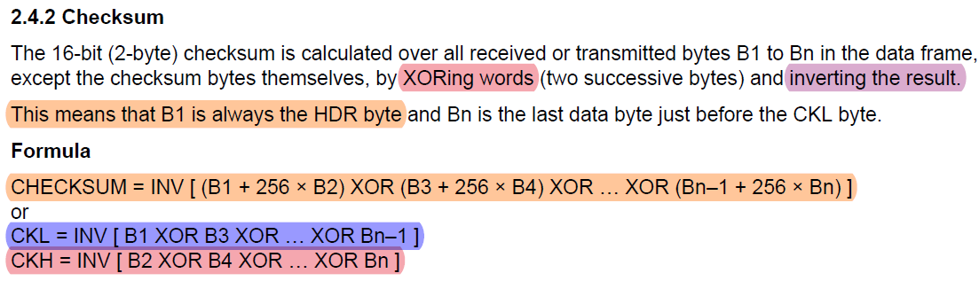
The biggest problem I'm facing right now is calculating the Checksum values (CKL | CKH)

The only place that mentions how to calculate the checksum values is the MSP430 Flash Device Bootloader (BSL) PDF in the Checksum section 2.4.2 (page 10) as listed below.

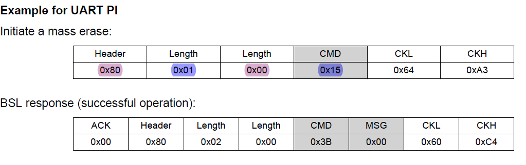
When I jump to the MSP430 FRAM Devices Bootloader (BSL) PDF to section 4.1.5.3 : Mass Erase (page 18) and scroll down to the Example for UART PI to have something to follow by, I'm not understanding how they got 0x64 and 0xA3 for the checksum bytes in comparison to the 0x7F and 0xEB bytes that I calculated using the CKL and CKH formulas in the screenshot above.

Below is the UART PI that was just mentioned.

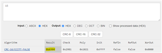
For complete transparency, here's what I did to calculate the checksum bytes (0x7F and 0xEB) I mentioned earlier

CKL = INV [ 0x80 XOR 0x00 ] --> INV [ 1000 0000 XOR 0000 0000 ] --> INV [ 1000 0000 ] --> 0111 111 --> 0x7F

CKH = INV [ 0x01 XOR 0x15 ] --> INV [ 0000 0001 XOR 0001 0101 ] --> INV [ 0001 0100 ] --> 1110 1011 --> 0xEB

Any guidance on the matter would be greatly appreciated 

  • The FRAM BSL calculates a CRC-16/CCITT-FALSE checksum. See 4.1.5.4, CRC Check, of the FRAM Devices BSL document. The fields in grey are the bytes used to calculate the CRC.

    Go to https://www.crccalc.com, set the input to HEX, insert "15" into the input, then click the "CRC-16" button. You will see the result on the page for "CRC-16/CCITT-FALSE" as "0xA364"; the FRAM BSL puts the CRC out as little-endian.

    CRC-16/CCITT-FALSE result

  • I appreciate your response Seth, but can you elaborate further on how you got 15 relative to the UART PI example prior entering that into the CRC calculator you mentioned?

    I'd assume after reading your response that you used the CHECKSUM formula that's highlighted in orange?

    Below are the steps I took with hopes of getting the same results, but I fell short and I'm not sure what I did wrong.

    CHECKSUM = INV [ (0x80 + 256 * 0x01) XOR (0x00 + 256 * 0x15)] (written out in HEX)
     
    CHECKSUM = INV [ (128 + 256 * 1) XOR (0 + 256 * 21) ] (written out in DECIMAL) 

    CHECKSUM = INV [ 384 XOR 5376 ]

    CHECKSUM = INV [ 5248 ]

    CHECKSUM = INV [ 0001 0100 1000 0000]

    CHECKSUM = 1110 1011 0111 1111 = 75BF (HEX) = 30143 (DECIMAL)

    Results after entering 75BF into crccal.com --> 0xBC97

  • No, the formula is completely different than what you highlighted in orange. The formula you found in the MSP430 Flash Device Bootloader (BSL) PDF is not applicable to your device.

    The CRC on an FRAM device is calculated with a CRC-16/CCITT-FALSE algorithm, not the formula you highlighted in orange. The FRAM BSL is simply using the CRC Module present inside the MCU to calculate. You may want to read the device's User Guide on the CRC Module to get an idea of how it's calculated.

    In the UART PI example, all of the fields shaded in dark grey are the bytes which are input into the CRC calculation. So for the "Mass Erase" command, only the CMD byte is in grey. Passing the CMD byte (0x15) into a valid CRC-16/CCITT-FALSE calculator will yield 0xA364. As such, the BSL's response calculates the CRC with the two bytes in grey, CMD (0x3B) and MSG (0x00). Placing these two bytes into a CRC-16/CCITT-FALSE calculator will result in a checksum of 0xC460.

    Here is a generic function which can be used as an EXAMPLE of how to calculate the CRC for your FRAM device. Byte or bit order changes the result, so it would need to be tailored to match correct endianness of the target and master devices.

    uint16_t calculateCRC16CCITTFALSEChecksum(unsigned char *byteBuffer, unsigned int numChars)
    {
    	int i = 0;
    	int j = 0;
    	uint16_t checksum = 0xFFFF;	
    	
    	for(i = 0; i < numChars; i++)
    	{		
    		checksum ^= (byteBuffer[i] << 8);
    		for(j = 0; j < 8; j++)
    		{
    			if(checksum & 0x8000)
    			{
    				checksum <<= 1;
    				checksum ^= 0x1021;//Represents the x^15 + x^12 + x^5 + 1 polynomial
    			}
    			else
    				checksum <<= 1;
    		}
    	}
    	
    	return checksum;
    }

  • You're my hero Seth

    This is my first time that I've ever written a bootloader program of any sort and your answer helped me finally progress on this project that's been dead in the water for the past month and a half

  • You're welcome! I was there too not too long ago. Make sure to carefully read SLAU550AA especially when you want to program your target through BSL. One of the more important things to note is there is a max payload size of 256 bytes per "RX Data Block" transaction, so you'll need to have multiple transactions if your MSP430 target's program is larger than 256 bytes.

**Attention** This is a public forum