This thread has been locked.

If you have a related question, please click the "Ask a related question" button in the top right corner. The newly created question will be automatically linked to this question.

Connecting a CC1101EMK to a MSP4302231

Other Parts Discussed in Thread: CC1101, SIMPLICITI, MSP430G2231, CC1100, CC2500, MSP430G2221

Hi there TI community, 

I am currently wondering the proper way to connect a CC1101 EMK to a MSP4302231.  My research has led me to believe that I need to code the MSP430 with TI's SimpliciTI wireless protical. I am wondering however how the CC1101EMK is programed directly out of the box because I do not have anyway of re-programming the CC1101 since I do not have a "SmartRF04EB" or  a "MSP-EXP430F4618" or a "SoC Battery Board". 

I have the CC1101EMK because I am trying to wirelessly receive acceleration data from an  EZ430-Chronos.

So far my wired connections between the MSP430 and the CC1101 are below 

Slave Master

CC1101 MSP430
-------------------------------- ------------------------------
P1.18  SDI        | <-------            | SDO       P1.6  |
| P1.20  SD0       | -------> |   SDI          P1.7 |
| P1.16  SCLK    |  <-------       | SCLK     P1.5 |

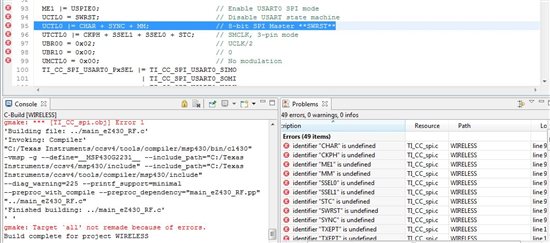
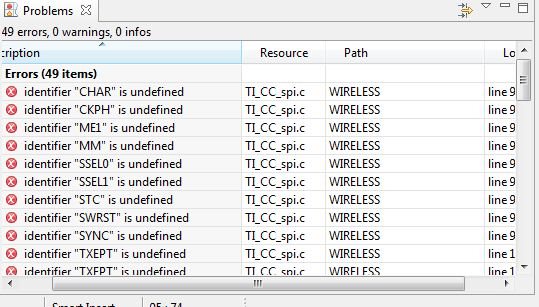
I am using the "msp430g2x21_usi_02.c" program which is "SPI full-Duplex 3-wire Master" and to my understanding it will interface with the CC1101 using it as a slave. So far however I have not been able to get the watch to sync with the CC1101EMK.  

1. Can anyone help me understand if I am on the right track so far?

2. If so what do I need to program the MSP430 with in order to get the system to sync with the Chronos watch?

Thanks in advance

--David

  • Hi David,

    I'm not a SimpliciTI user or a Chronos user, but nobody has answered you yet.

    There are four SPI modes (typically 0, 1, 2, and 3) and you must pick the correct one for your slave.  In the case of the CC1101, it expects the clock to idle low (USICKPL = 0) and the first edge (the rising edge) to latch data (USICKPH = 1).  You'll have to modify the example code from TI to use those settings.

    Also the CC1101 requires a chip select signal, CSn.  You'll need to attach one more signal between the MSP430 and the CC1101 to serve this role.  Your software will have to handle the CSn signal manually.  The CSn signaling is also part of some non-standard handshaking.  After you assert CSn, you must wait for the CC1101 SO pin to go low before starting the USI transfer.

    It is a 4-wire configuration, but even if you started with the example for a 4-wire slave, you'd have to customize the code to account for the special handshaking.

    Maybe there's a TI library somewhere for using the USI with the CC1101?  It's worth looking for.

    Jeff

  • In addition to Jeffs post, I might add that there should be some sort of chip select signal.
    On the master side, it is a normal GPIO pin, but it synchronizes the slave to the transfer start. Since SPI is a bus, there may be more than one slave. Also, it is bit-synchronous, so you don't knwo where a byte (or a whole protocol) starts. This is where you need the chip select. When it goes low, it means that the next clock pulse is for the first bit of a new transmission to and from this single slave. All other slaves with their chip select signal high, will stay silent and ignore the bus completely.

    I cannot help you with the high-level chronos stuff. But except for the low-level SPI interface access, the Chronos code should tell you everything you need.

  • Thanks for responding Jeff, 

    Also I have found the PDF for "Interfacing the MSP430 with CC1100-2500" 
    LINK1: http://focus.ti.com/lit/an/swra116a/swra116a.pdf 

    I have recently, after more research and reading this document, found some TI code that interfaces the CC1101 with MSP430Fxxxx boards.
    LINK2: http://focus.ti.com/general/docs/lit/getliterature.tsp?baseLiteratureNumber=slaa325&fileType=zip


    I can just set up the SPI interface using the connections on page 7 of the PDF pins (from P2.4-P5)  and then alter the code in the TI library in order to change it to the registers and output pins on the MSP430 right? Because all its doing is interfacing the connections between the CC1101 and the SmartRF04EB. 

    also I have the Chronos watch sending data using the SimpliciTI wireless protocol so once I set up the SPI interface between the CC1101 and the MSP430 do I need to figure out how to install SimpliciTI onto the MSP430 in order to get the watch to sync?

    all of this stuff is very new to me so any and all advice is much appreciated. 

    Thanks, 
    David 

  • After reading the PDF MSP430 interface to CC1101 Code Library I have tried to edit the code libraries. 

    On page 6 section 5.3 it describes the way to "Adapt the demo project to other hardware" I have followed these directions to the best of my knowledge. At this point I am just trying to get the demo code working with 2 transmitter boards and 2 MSP430G2231 boards. 

    Step 1: I changed the filename in the #include file reference at the top of the TI_CC_MSP430.h  and made it MSP430g2231.h

    Step 2: I decided to modify the // SPI port definitions to the code below because the pin outs on the MSP430 TX/RX are on the pin1.1/2 respectively.              

    CODE:

    // Adjust the values for the chosen

    #define TI_CC_SPI_USART0_PxSEL  P1SEL       // interfaces, according to the pin

    #define TI_CC_SPI_USART0_PxDIR  P1DIR       // assignments indicated in the

    #define TI_CC_SPI_USART0_PxIN   P1IN        // chosen MSP430 device datasheet.

    #define TI_CC_SPI_USART0_SIMO   BIT1

    #define TI_CC_SPI_USART0_SOMI   BIT2

    #define TI_CC_SPI_USART0_UCLK   BIT5

    Step 3:  I changed the pin assignments in TI_CC_hardware_board.h since GDO1/2 are not used I did not change them 

    CODE:


    //----------------------------------------------------------------------------

    //  Description:  This file contains definitions specific to the hardware board.

    //  Specifically, the definitions include hardware connections with the

    //  CCxxxx connector port, LEDs, and switches.

    //

    //  MSP430/CC1100-2500 Interface Code Library v1.0

    //

    //  K. Quiring

    //  Texas Instruments, Inc.

    //  July 2006

    //  IAR Embedded Workbench v3.41

    //----------------------------------------------------------------------------


    #define TI_CC_LED_PxOUT         P1OUT

    #define TI_CC_LED_PxDIR         P1DIR

    #define TI_CC_LED1              0x01

    #define TI_CC_LED2              0x06

    #define TI_CC_LED3              0x04

    #define TI_CC_LED4              0x08


    #define TI_CC_SW_PxIN           P1IN

    #define TI_CC_SW_PxIE           P1IE

    #define TI_CC_SW_PxIES          P1IES

    #define TI_CC_SW_PxIFG          P1IFG

    #define TI_CC_SW_PxREN          P1REN

    #define TI_CC_SW_PxOUT          P1OUT

    #define TI_CC_SW1               BIT3

    #define TI_CC_SW2               BIT2

    #define TI_CC_SW3               0x40

    #define TI_CC_SW4               0x80


    #define TI_CC_GDO0_PxOUT        P1OUT

    #define TI_CC_GDO0_PxIN         P1IN

    #define TI_CC_GDO0_PxDIR        P1DIR

    #define TI_CC_GDO0_PxIE         P1IE

    #define TI_CC_GDO0_PxIES        P1IES

    #define TI_CC_GDO0_PxIFG        P1IFG

    #define TI_CC_GDO0_PIN          0x04


    #define TI_CC_GDO1_PxOUT        P5OUT

    #define TI_CC_GDO1_PxIN         P5IN

    #define TI_CC_GDO1_PxDIR        P5DIR

    #define TI_CC_GDO1_PIN          0x10


    #define TI_CC_GDO2_PxOUT        P2OUT

    #define TI_CC_GDO2_PxIN         P2IN

    #define TI_CC_GDO2_PxDIR        P2DIR

    #define TI_CC_GDO2_PIN          0x40


    #define TI_CC_CSn_PxOUT         P1OUT

    #define TI_CC_CSn_PxDIR         P1DIR

    #define TI_CC_CSn_PIN           BIT5


    //----------------------------------------------------------------------------

    // Select which port will be used for interface to CCxxxx

    //----------------------------------------------------------------------------

    //#define TI_CC_RF_SER_INTF       TI_CC_SER_INTF_BITBANG  // Interface to CCxxxx


    //#define TI_CC_RF_SER_INTF       TI_CC_SER_INTF_USCIB0  // Interface to CCxxxx


      #define TI_CC_RF_SER_INTF       TI_CC_SER_INTF_USART0  // Interface to CCxxxx


    //

    STEP 4: I then assigned the proper values to TI_CC_RF_SER_INTF in the TI_CC_hardware_board.h which is shown directly above

     I tried to debug and run this code and I run into errors when the code tries to initialize the SPI bus pictured below:


    Am I missing an include file somewhere or something? 

    I hope that I am not posting to many questions at a time, please let me know if I am. 

    Thanks for the assistance so far 
    --David 

  • Looks like it's compiling for the wrong serial device.  I don't know the code, but I just scanned it quickly to find that you probably need to set

    TI_CC_RF_SER_INTF to be TI_CC_SER_INTF_USI

    in TI_CC_hardware_board.h

    Jeff

  • Update: I was able to get a serial connecting working between the MSP430G2231 and the CC1101 but I am still not able to get the Chronos watch to sync with the receiver. 

  • Good news about the serial link.  Did you use TI_CC_SER_INTF_USI to get it working?

    It seems that now the last step is installing the SimpliciTI protocol onto your G2231 device and perhaps writing a small amount of application code to receive whatever data you are trying to receive from the Chronos watch.  Hopefully somebody else can help you out there since I don't use either (SimpliciTI or Chronos).

    Here's a link to the simpliciTI protocol stack.  http://focus.ti.com/docs/toolsw/folders/print/simpliciti.html   There are two different versions, so be sure to get the one for CC1101.

    Good luck!

    Jeff

  • Jeff, 

    I did set it to  TI_CC_SER_INTF_USI

    I changed the pins according to LINK: http://blog.hodgepig.org/2010/09/10/575/  which outlined how to setup the MSP430 with a SPI connection. 

    CC1101 MSP430G2231

    _____________ _______________
    pin
    SI <---------  1.4 
    GDO0------> 1.1
    SCLK<----- 1.7
    CSn<------->  1.2
    SO---------->  1.5 

    Defined in  TI_CC_hardware_board.h

    #define TI_CC_LED1             BIT0
    #define TI_CC_LED2             BIT6
    #define TI_CC_SW1               BIT3

    #define TI_CC_GDO0_PIN       BIT1

    #define TI_CC_CSn_PIN          BIT2


    The following are defined in TI_CC_msp430.h

    #define TI_CC_SPI_USART0_SIMO    BIT4
    #define TI_CC_SPI_USART0_SOMI    BIT5
    #define TI_CC_SPI_USART0_UCLK   BIT7
    #define TI_CC_RF_SER_INTF       TI_CC_SER_INTF_USI  // Interface to CCxxxx 

    GDO1, GDO2 are not used in the example so I did not assign them IN/OUT pins on the MSP430

    I have not been able to try out the demo program yet because I do not have my hands on another MSP430G2231. I will check out the link you left and try to get the Chronos working with this SPI setup. Thanks for all the help so far Jeff, I'll keep you posted on my progress. 

  • I set up my code on 2 MSP430 launchpads each connected to a CC1101EMK I tried running the demo code without any success. I looked and the code that I have is for the CC1100 so I tried to update the file

    "CC1100 - CC2500.c" I opened up Smart RF Studio, Set the target frequency to 433Mhz (my watch's frequency) , found the registers that it used and changed the registers in the CC100-CC2500.c file. Unfortunately after these changes I was still unable to get the MSP430's communicating.

    I have been comparing the original setup code and my code and I'm wondering does the MSP430g2231 have a STE port, and could this be causing me problems?

    The MSP430F16x has an STE1 and the MSP430G2231 does not have a pin named the "STE" and I'm not sure if that matters or if it can just be assigned.

    I changed the pin-outs to the following just to ensure that each pin could support the function that I had assigned it by using the code setup from the example code here
    http://blog.hodgepig.org/2010/09/10/575/

    CC1101 ---- MSP430

    GDO0------   1.1
    GDO2-----    1.2
    CSn---------   1.4
    SCLK-------    1.5
    SI-----------     1.3
    SO----------    1.7

    Is there anyway that the pins that I have assigned are not able to support the function that I have given them?

  • While I can't comment on the code in the SimpliciTI stack or their sample application, I can tell you that the only pins that must be assigned to a specific pin are SI, SO, and SCLK.  The CSn and GDOn pins are flexible.  The SI signal must go to the MSP430 MOSI (SIMO) pin, and the SO signal must go to the MSP430 MISO (SOMI) pin.  And SCLK to SCLK.  The CC1101 driver you're using requires those three signals to be in the right place because you configured the driver to use the USI (not to bit bang).  That was a good choice.

    And no, you don't need an STE pin.  That pin is used by the MSP430 when it is in 4-wire slave mode.  Your MSP430 is in master mode.

    Maybe you could start another thread to get help on the SimpliciTI stack?  I promise not to answer that one.  ;-)


  • hi david, i am also working on a similar ground as you.I need SPI interface between my msp430g2231 and CC1101 transciever.my question is do we need a select signal if we are using only one slave(CC1101) and what are primary changes that need to be made in the SPI-master code,its a bit confusing.


    thanks in advance

    --sanchay


  • well from experience let me tell you up front, if you are trying to do this for a senior design project (3 month time limit) Don't do it. Find another way. I ended up scrapping the MSP-430 to CC1101 after 2.5 months of working on just the SPI interface. it may have been my inexperience however it eats up valuable time. 

    What I ended up doing was connecting the USB receiver from the Chronos watch up to a FEZ domino board. This eliminated the need to deal with the wireless connections completely.

    good luck on what you decide on

    --David H 

  • OK...out of curiousty  are there any passives needed for connection between the msp430 and the CC1101?..if any can you give some details about it..


    thanks in advance

    sanchay arora

  • well everything i know or that i tried for this project i tried to document on this page. every document that i found is here. I was never able to get it working so if you are successful let me know what you did. 


    good luck

    --david

  • sorry to bother you again Mr. david but i am facing a problem...i m trying to execute 8 bit SPI between two msp430g2231 launchpad boards...but i m a bit confused with the sample code...according to the sample code for 3-wire SPI  the level on P1.4 is TX'ed and RX'ed to P1.0. Is the level transmission a sign to show that an 8 bit data has transmitted or the level transmission is the operation being performed by the SPI....confusion is there because of the use of the USISRL register...can u plz help with this..the sample code is as follows-

    //******************************************************************************

    //  MSP430G2x21/G2x31 Demo - SPI full-Duplex 3-wire Master

    //

    //  Description: SPI Master communicates full-duplex with SPI Slave using

    //  3-wire mode. The level on P1.4 is TX'ed and RX'ed to P1.0.

    //  Master will pulse slave reset for synch start.

    //  ACLK = n/a, MCLK = SMCLK = Default DCO

    //

    //                Slave                      Master

    //             MSP430G2x21/G2x31          MSP430G2x21/G2x31

    //             -----------------          -----------------

    //            |              XIN|-    /|\|              XIN|-

    //            |                 |      | |                 |

    //            |             XOUT|-     --|RST          XOUT|-

    //            |                 | /|\    |                 |

    //            |          RST/NMI|--+<----|P1.2             |

    //      LED <-|P1.0             |        |             P1.4|<-

    //          ->|P1.4             |        |             P1.0|-> LED

    //            |         SDI/P1.7|<-------|P1.6/SDO         |

    //            |         SDO/P1.6|------->|P1.7/SDI         |

    //            |        SCLK/P1.5|<-------|P1.5/SCLK        |

    //

    //  D. Dang

    //  Texas Instruments Inc.

    //  October 2010

    //  Built with CCS Version 4.2.0 and IAR Embedded Workbench Version: 5.10

    //******************************************************************************


    #include <msp430g2221.h>


    void main(void)

    {

      volatile unsigned int i;


      WDTCTL = WDTPW + WDTHOLD;             // Stop watchdog timer

      P1OUT =  0x10;                        // P1.4 set, else reset

      P1REN |= 0x10;                        // P1.4 pullup

      P1DIR = 0x01;                         // P1.0 output, else input

      USICTL0 |= USIPE7 +  USIPE6 + USIPE5 + USIMST + USIOE; // Port, SPI master

      USICTL1 |= USIIE;                     // Counter interrupt, flag remains set

      USICKCTL = USIDIV_4 + USISSEL_2;      // /16 SMCLK

      USICTL0 &= ~USISWRST;                 // USI released for operation

      USISRL = P1IN;                        // init-load data


      P1DIR |= 0x04;                        // Reset Slave

      P1DIR &= ~0x04;

      for (i = 0xFFF; i > 0; i--);          // Time for slave to ready

      USICNT = 8;                           // init-load counter

      _BIS_SR(LPM0_bits + GIE);             // Enter LPM0 w/ interrupt

    }


    // USI interrupt service routine

    #pragma vector=USI_VECTOR

    __interrupt void universal_serial_interface(void)

    {

      if (0x10 & USISRL)

        P1OUT |= 0x01;

      else

        P1OUT &= ~0x01;

      USISRL = P1IN;

      USICNT = 8;                           // re-load counter

    }


    thanking you in advance

    sanchay arora

  • How did u do that? Would u mind showing me how did you fix this problem? I am currently stuck into this part. Thanks.

**Attention** This is a public forum