Other Parts Discussed in Thread: EVM430-FR6043
Hi Team,
Good day. I am posting this inquiry on behalf of our customer.
We're developing a water flowmeter using MSP430FR50431 and USS library supplied by you. We have managed to create a USS configuration and firmware suitable for our application, but we have encountered a possible bug while developing our own frequency sweep function similar to the one in Ultrasonic Sensing Design Center software.
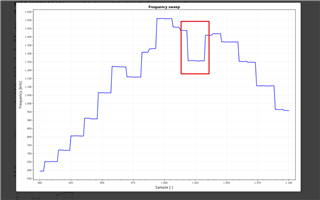
Our goal is to create a function inside the firmware, which will tune the frequency to the best value for transducers attached to it, however, from our observation the data don't form a smooth curve, but rather something resembling "steps" (axis captions are switched by accident, X-axis is in fact frequency, Y-axis is signal amplitude).
Frequency sweep was performed on 900kHz - 1100kHz range with 1kHz step:
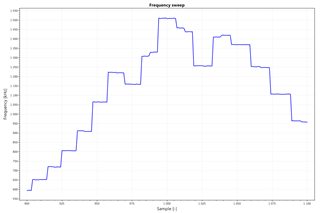
Thinking this was a bug on our side, we have performed a similar frequency sweep using EVM430-FR6043 development kit modified for water applications and Ultrasonic Sensing Design Center software. Test was performed on 950kHz - 1050kHz range with 1kHz step. Transducers weren't the same as during the first test, but were from the same batch. Software has returned following result:
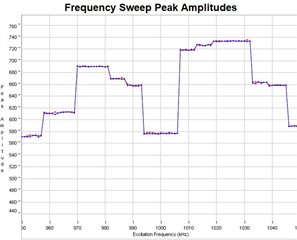
From our point of view, this seems like some problem with frequency multipliers/dividers inside the peripheral causing it not to switch the excitation frequency by 1kHz, but rather by 5-7kHz.
In our software we have tested various ways to overcome this problem, like giving the USS library more dummy USS flowrate readouts to stabilize the frequency or setting the frequency in pseudo-random order, however, nothing seems to fix this issue. We have run this frequency sweep on more than 100 devices and the behavior is the same on all of them.
We're using an 8MHz crystal oscillator as a source for USS peripheral.
Can you please give us some advice on how to force the peripheral to properly switch the transducer excitation frequency according to configuration?
Please help to advise. Thank you for extending your support.
Kind regards,
Marvin