This thread has been locked.

If you have a related question, please click the "Ask a related question" button in the top right corner. The newly created question will be automatically linked to this question.

MSP430FG6426: CTSD16: internal temp sensor not working?, voltage ranges

Part Number: MSP430FG6426
Other Parts Discussed in Thread: MSP430WARE, MSP-TS430PZ100AUSB, MSP430FR2355

Hi Gurus,

We use an MSP430FG6426 for the CTSD16, to measure a few voltages. We are trying to establish from first principles what is the input voltage range. And by the looks of it we can not even reliably measure the the internal temperature with the example codes.

On our board we are using single ended inputs and P5.0 is through a 1nF cap connected to AVSS. And no internally programmed gain.

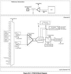
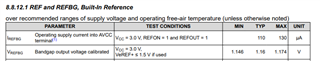
What is the reference voltage?  According to various places in the datasheet and the programming guide (www.ti.com/.../slau208q.pdf) there is mention of VEREF in module 26. 

There is mention that P5SEL should be set to 1, while setting in REFCTL: REFON, REFOUT, REFMSTR. But there are some confusing statements that the VEREF module can change the reference voltage 

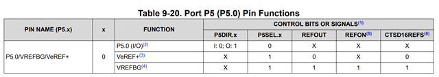
Wed didn't know about the P5SEL for a while, so we've never set it, and it never seems to have any impact what's happening.

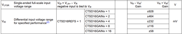
So the ultimate question is if the reference voltage is a fixed 1.16V, then what is the voltage range for a single ended input? 2.32V? If so how do you map the 16bit MSB (I guess independent of the oversampling rate) to voltage values? (With 2's complements)

I apply 100mV (above AVSS), what is the expected CTSD16MEM0 content? Assume LSBACC=0.

100mV/2320mV * 32768 = 1412? 

Why is there a different full scale range and a specified performance range?

-----------------

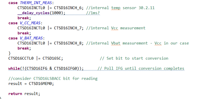
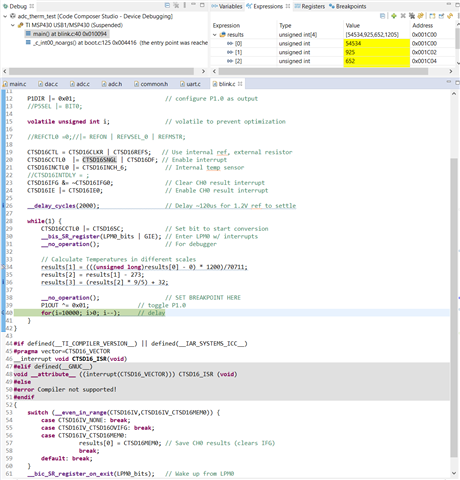
The below code is almost identical to msp430fg662x_ctsd16_06.c in c:\ti\msp430ware_3_80_14_01\examples\devices\MSP430F5xx_6xx\MSP430FG662x_MSP430FG642x_Code_Examples\C\ Only added a little bit of LED blinking.

The below code is run by wiring an MSP430FR2355 Launchpad to the MSP-TS430PZ100AUSB Launchpad. Obviously we only use the former for debugging capability. By looking at the latter's schematics it is not grounded through a 1nF cap, but a 100nF and a 10uF. The two boards are connected through SBWTDIO/TCK.

You can see it below as I stopped the debugger that the temperature is calculated to be 925Kelvin, which is obviously incorrect. Power cycling the board sometimes yields a totally different number.

Any ideas what is happening and why this would not be working?

Thanks for your help!

Peter

  • Hello Peter,

    1. The CTSD peripheral uses the Vrefbg for its reference voltage, so the typical value is 1.16V
    2. There is another reference voltage on the device is used for the DAC.
    3. The FSR for "single ended" configuration is , so with no gain you will have from 0 to 2x the reference (which is 2.32V)
    4. The full-scale range formula is given and fully used when using an external reference. The "for specified performance" is when using the internal reference as it is recommended to use only 80% of the FSR. Footnote (2) explains this further. 
    5. The example code requires an external resistor for that configuration. You can change the configuration to not use an external resistor on line 103 (the external resistor is associated with the CTSD CLK). The temperature sensor also has an offset associated with it (±100 mV) though that should only be ~50 Kelvin.

    Regards,

    Luke

  • Hi Luke,

    Thanks very much for your multiple answers.

    So altogether

    0v is 0x0 in 2s complements.

    And

    2.32V is 0x7FFF in counts (reading only MSB), right?

    I'll give the internal thermistor a try next week when I'm at my desk.

    Is the calibration which is supposed to solve that 100mV uncertainty?

    Cheers,

    Peter

  • Hi Peter,

    In the peusdo-single ended operation the range for 2's complement would be:

    • 0 at 0x8000 
    • Reference (1.16V) at 0x0000
    • 2x Reference (2.32V) at 0x7FFF

    I don't recommend 2's complement though since your signal range would be from 0-2Ref. 2's complement is more used to help represent negative numbers. The offset binary format fits your application better.

    By doing a calibration you can compensate for the offset.

    Regards,

    Luke

  • Hi Luke,

    1) I've tested on the Launchpads with removing the CTSD16CLKR bit (and removing 2's complements as well), which btw seems undocumented in https://www.ti.com/lit/ug/slau208q/slau208q.pdf 

    But there seems to be no difference whatsoever. With regards to the uncertainty +-100mV should be +-50K, right?

    Also there is a mention of needing to add a delay in "30.2.11 Using the Integrated Temperature Sensor". What if we don't use an interrupt (see #3)? How much delay is that?

    Any ideas what is happening?

    2) I've been reviewing your comments on the binary format of the ADC ticks. It is interesting that in this case negatives are not represented. The only reason I've considered 2's complements is that I thought that negatives will still be represented (as per 30.2.8.1 Output Data Format), just not used. We will not use 2's complements going forward.

    3) In which circumstances should we use CTSD16INTDLY? Currently in our code we do not use an interrupt, but after CTSD16SC we wait for IFG0 bit to be set. Is this ok, or should we do it in another way?

    4) Due to the range being 0->2.32V I presume we can not use this to measure Vcc. Do you have a recommended method to do that?

    5) Is the calibration done in the factory or we should do that manually? Is this code a fair way to read the values? https://github.com/Andy4495/MspTandV/blob/main/src/MspTandV.cpp Does this even work with FG6426?

    Thanks,

    Peter

  • Hi Peter,

    I looked further into this example code and it is incorrect. The TLV data (this is found in the datasheet) contains the calibration values for the CTSD16 and also with regards to the internal temperature sensor. 

    Looking at the MSPFR413x_adc10 temperature example, we can use the same process with this device and the calibration data stored in the TLV data. Here are the steps I took to convert the MSPFG6426 example.

    1. Find the memory location for the temperature calibration data found in the TLV table
    2. Create #define for the memory addresses for ease of reading
      1. #define CALADC_30C *((unsigned int *) 0x1A1E)
      2. #define CALADC_85C *((unsigned int*) 0x1A20)
    3. Since we are using the calibration data we need to change our formulas, these calibration values are based on Celsius.
    4. Here are the equations based on the FR413x example
    5. results[1] = (results[0] -  CALADC_30C) * (85-30) / (CALADC_85C - CALADC_30C) + 30
      results[2] = results[4] * 9/5 + 32;

    Below I'll post the whole code section so you can copy and paste to test yourself.

    /* --COPYRIGHT--,BSD_EX
     * Copyright (c) 2014, Texas Instruments Incorporated
     * All rights reserved.
     *
     * Redistribution and use in source and binary forms, with or without
     * modification, are permitted provided that the following conditions
     * are met:
     *
     * *  Redistributions of source code must retain the above copyright
     *    notice, this list of conditions and the following disclaimer.
     *
     * *  Redistributions in binary form must reproduce the above copyright
     *    notice, this list of conditions and the following disclaimer in the
     *    documentation and/or other materials provided with the distribution.
     *
     * *  Neither the name of Texas Instruments Incorporated nor the names of
     *    its contributors may be used to endorse or promote products derived
     *    from this software without specific prior written permission.
     *
     * THIS SOFTWARE IS PROVIDED BY THE COPYRIGHT HOLDERS AND CONTRIBUTORS "AS IS"
     * AND ANY EXPRESS OR IMPLIED WARRANTIES, INCLUDING, BUT NOT LIMITED TO,
     * THE IMPLIED WARRANTIES OF MERCHANTABILITY AND FITNESS FOR A PARTICULAR
     * PURPOSE ARE DISCLAIMED. IN NO EVENT SHALL THE COPYRIGHT OWNER OR
     * CONTRIBUTORS BE LIABLE FOR ANY DIRECT, INDIRECT, INCIDENTAL, SPECIAL,
     * EXEMPLARY, OR CONSEQUENTIAL DAMAGES (INCLUDING, BUT NOT LIMITED TO,
     * PROCUREMENT OF SUBSTITUTE GOODS OR SERVICES; LOSS OF USE, DATA, OR PROFITS;
     * OR BUSINESS INTERRUPTION) HOWEVER CAUSED AND ON ANY THEORY OF LIABILITY,
     * WHETHER IN CONTRACT, STRICT LIABILITY, OR TORT (INCLUDING NEGLIGENCE OR
     * OTHERWISE) ARISING IN ANY WAY OUT OF THE USE OF THIS SOFTWARE,
     * EVEN IF ADVISED OF THE POSSIBILITY OF SUCH DAMAGE.
     *
     *******************************************************************************
     *
     *                       MSP430 CODE EXAMPLE DISCLAIMER
     *
     * MSP430 code examples are self-contained low-level programs that typically
     * demonstrate a single peripheral function or device feature in a highly
     * concise manner. For this the code may rely on the device's power-on default
     * register values and settings such as the clock configuration and care must
     * be taken when combining code from several examples to avoid potential side
     * effects. Also see www.ti.com/grace for a GUI- and www.ti.com/msp430ware
     * for an API functional library-approach to peripheral configuration.
     *
     * --/COPYRIGHT--*/
    //******************************************************************************
    //  MSP430FG662x Demo - CTSD16, Using the Integrated Temperature Sensor, Ext. Res.
    //
    //  Description: This program uses the CTSD16 module to perform a single
    //  conversion on a single channel which is internally connected to the CTSD16's
    //  temperature sensor and an external resistor feeding the CTSD16 clock. Once
    //  the conversion is completed, the result is stored in a variable then converted
    //  into Celsius and Fahrenheit values.
    //
    //  Test by setting a breakpoint at the indicated line. Upon reaching the breakpoint
    //  the conversion result will be stored in the results array. The result will
    //  then be taken and converted into degrees K, C, and F and be saved in the same
    //  array.
    //
    //  ACLK = 32kHz, MCLK = SMCLK = Calibrated DCO = 16.384MHz, SD_CLK = 1.024MHz
    //  * Ensure low_level_init.c is included when building/running this example *
    //
    //  Notes: For minimum Vcc required for CTSD16 module - see datasheet
    //         1nF cap btw Vref and AVss is recommended when using 1.2V ref
    //
    //  Sensor's temperature coefficient is 2.158mV/K (from datasheet)
    //  Sensor's offset voltage ranges from -100mv to 100mV (assume 0)
    //  Vsensor = 1.32mV * DegK + Vsensor_offset (assuming 0mv for offset)
    //  Vsensor = (CTSD16MEM0)/32767 * Vref(mV)
    //  DegK = (CTSD16MEM0 * 1200)/32767/2.158 = (CTSD16MEM0 * 1200)/70711
    //  DegC =  DegK - 273
    //  DegF = (DegC * 9/5) + 32
    //
    //
    //               MSP430FG662x
    //             -----------------
    //         /|\|                |
    //          | |                |
    //          --|RST             |
    //            |                |        (A0.6+/- connected internally)
    //            |A0.6+      VREF |---+    (to CTSD16's temperature sensor)
    //            |A0.6-           |   |
    //            |                |  -+- 1nF
    //            |                |  -+-
    //            |                |   |
    //            |           AVss |---+
    //
    //  M. Swanson
    //  Texas Instruments, Inc
    //  April 2014
    //  Built with Code Composer Studio v5.5
    //******************************************************************************
    #include <msp430.h>
    #define CALADC_30C *((unsigned int *) 0x1A1E)
    #define CALADC_85C *((unsigned int*) 0x1A20)
    unsigned int  results[3];                   // CTSD16 Conversion and Temp Results
                                                // results[0] = raw CTSD16 results
                                                // results[1] = temp in C
                                                // results[2] = temp in F
    
    void main(void) {
        WDTCTL = WDTPW | WDTHOLD;               // Stop watchdog
    
        CTSD16CTL = CTSD16CLKR | CTSD16REFS;   // Use internal ref, external resistor
        CTSD16CCTL0  |= CTSD16SNGL; //| CTSD16DF; // Enable interrupt
        CTSD16INCTL0 |= CTSD16INCH_6;           // Internal temp sensor
        CTSD16IFG &= ~CTSD16IFG0;               // Clear CH0 result interrupt
        CTSD16IE |= CTSD16IE0;                  // Enable CH0 result interrupt
    
        __delay_cycles(2000);                   // Delay ~120us for 1.2V ref to settle
    
        while(1) {
            CTSD16CCTL0 |= CTSD16SC;            // Set bit to start conversion
            __bis_SR_register(LPM0_bits | GIE); // Enter LPM0 w/ interrupts
            __no_operation();                   // For debugger
    
            // Calculate Temperatures in different scales
            results[1] = (results[0] -  CALADC_30C) * (85-30) / (CALADC_85C - CALADC_30C) + 30;
            results[2] = results[4] * 9/5 + 32; 
            __no_operation();                   // SET BREAKPOINT HERE
        }
    }
    
    #if defined(__TI_COMPILER_VERSION__) || defined(__IAR_SYSTEMS_ICC__)
    #pragma vector=CTSD16_VECTOR
    __interrupt void CTSD16_ISR(void)
    #elif defined(__GNUC__)
    void __attribute__ ((interrupt(CTSD16_VECTOR))) CTSD16_ISR (void)
    #else
    #error Compiler not supported!
    #endif
    {
        switch (__even_in_range(CTSD16IV,CTSD16IV_CTSD16MEM0)) {
            case CTSD16IV_NONE: break;
            case CTSD16IV_CTSD16OVIFG: break;
            case CTSD16IV_CTSD16MEM0:
                       results[0] = CTSD16MEM0; // Save CH0 results (clears IFG)
                       break;
            default: break;
        }
        __bic_SR_register_on_exit(LPM0_bits);   // Wake up from LPM0
    }
    

    I was incorrect about the data format, 2's complement would be needed because the calibration data is formed on based on 2's complement. There is also an offset, which is not calibrated. If you do your own calibration I do recommend the offset version instead of 2's complement.

    Regards,

    Luke Ledbetter

  • Hi Luke,

    Thanks a lot for that!

    1) The temperature seems to be changing as expected now! 30C normal and rising to 40C when put under heating. I presume for negative numbers we just need to change result to integer. After running a bit longer every 5-10th read comes up with not 30C but 47C. Any ideas what is happening there? Since we are not using interrupt we don't use CTSD16INDLY.

    2) What would be the formula to use for CTSD16 calibration? I do not mind either data format. We use no gain. If we would be happen to use a gain which is not 1 and 16. How do you calculate that?

    3) Do you have any other suggestion to achieve highest DAC & ADC precision? Both from code and hardware perspective. I already see from the datasheet that (a) using a higher precision external reference voltage would help both (currently +-1% precision), as well as (b) using the CTSD16 calibration and (c) OSR==256.

    4) In which circumstances should we use CTSD16INTDLY? Currently in our code we do not use an interrupt, but after CTSD16SC we wait for IFG0 bit to be set (code in previous post). Is this ok, or should we do it in another way?

    Thanks a lot!

    Peter

  • Hi Peter,

    1. I would try to add the oversampling to see if this removes/reduces the 47C reading, my first theory would be noise so oversampling should alleviate the variance. The CTSD16INDLY bit is used for when the interrupt is generated, writing a 0 would have the interrupt after the fourth sample, a 1 would be the first sample.
      1. If you are not using an interrupt when/how are you getting the results? Are you polling the register?
    2. For the temperature sensor calibration it is recommended to do a single-point calibration. This means to take a reading at a known exact temperature and store the reading. You would then change the formula to base the value off the calibrated point.
      1. For example, if you have a known value of 0x3FFF at 25C, then you can calculate the value of your new temperature using that point as a reference.
    3. For general ADC precision there is signal conditioning that you can do on the hardware level with filtering of the AC signal. Also maintaining good board practice. If you want an in depth learning I recommend watching the TI Precision lab videos on ADC's, specifically the ADC noise videos. For software, sampling time and oversampling are the main ways to get good ADC results.
    4. The interrupt delay can be used when you want your results quicker by setting the interrupt to fire on the first sample. This is also helpful if you use the DMA and want to quickly perform math on the results. I personally prefer the interrupt based version as you can get the results as soon as they are available and it saves code time by not having to check the register each loop.

    Regards,

    Luke

  • Oh I forgot to mention how to read the AVCC. There is a voltage monitor (AVCC Sense) which will read the AVCC/2 for the device. The setup is similar to the internal temperature sensor. There is also a sensor for the VBAT if needed, this setup is included in the User's Guide.

    Regards,

    Luke

  • Hi Luke,

    Thanks for all those. I'll respond to those when I've tested all.

    Just quickly, regarding #2. My question was concerning the general ADC usage case. How to use the calibration data to increase precision of the CTSD16?

    Thanks,

    Peter

  • Hi Peter,

    I recommend reading section 1.13 in the User's Guide for information on using the TLV data. Below is a snippet for the ADC and CTSD16 Offset and Gain calibration. Slightly below this is a similar setup for the Temperature sensor.

    Regards,

    Luke

  • Thanks Luke for all your quick help. The temp sensor seems to be working well now! I've also implemented the ADC calibration values, though it seems to have skewed the results a bit more than before. Though I need to do more work on whether it is coming from somewhere else in the signal chain or not.

**Attention** This is a public forum