Hi all,
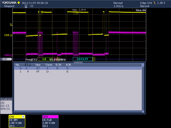
I'm working on MSP430G2252 to configure an I2C slave. I can't avoid that SCL line is held low by my slave : that cause a later answer of my slave
I tried different options but none works. Here below are two different codes, and after than an images of I2c bus transaction. (First SCL line, below SDA line)
thaks in advance
void main(void)
{
WDTCTL = WDTPW + WDTHOLD; // Stop watchdog
if (CALBC1_1MHZ ==0xFF || CALDCO_1MHZ == 0xFF)
{
while(1); // If calibration constants erased
// do not load, trap CPU!!
}
BCSCTL1 = CALBC1_1MHZ; // Set DCO
DCOCTL = CALDCO_1MHZ;
P1OUT = 0xC0; // P1.6 & P1.7 Pullups
//P1REN |= 0xC0; // P1.6 & P1.7 Pullups
P1DIR = 0xFF; // Unused pins as outputs
P2DIR = 0xFF; // Unused pins as outputs
USICTL0 = USIPE6+USIPE7+USISWRST; // Port & USI mode setup
USICTL1 = USII2C+USIIE+USISTTIE; // Enable I2C mode & USI interrupts
USICKCTL = USICKPL; // Setup clock polarity
USICNT |= USIIFGCC; // Disable automatic clear control
USICTL0 &= ~USISWRST; // Enable USI
USICTL1 &= ~USIIFG; // Clear pending flag
__enable_interrupt(); // Enable interrupts.
while(1)
{
}
}
//******************************************************
// USI interrupt service routine
//******************************************************
#pragma vector = USI_VECTOR
__interrupt void USI_TXRX (void)
{
if (USICTL1 & USISTTIFG) // Start entry?
{
P1OUT ^= LED1; // Toggle P1.0 using exclusive-OR
I2C_State = 2; // Enter 1st state on start
}
switch(I2C_State)
{
case 0: //Idle, should not get here
break;
case 2: //RX Address
USICNT = (USICNT & 0xE0) + 0x08; // Bit counter = 8, RX Address
USICTL1 &= ~USISTTIFG; // Clear start flag
I2C_State = 4; // Go to next state: check address
break;
..........................
.........................
}
USICTL1 &= ~USIIFG; // Clear pending flags
}
-------------- other code
void main(void)
{
WDTCTL = WDTPW + WDTHOLD; // Stop watchdog
if (CALBC1_1MHZ ==0xFF || CALDCO_1MHZ == 0xFF)
{
while(1); // If calibration constants erased
// do not load, trap CPU!!
}
BCSCTL1 = CALBC1_1MHZ; // Set DCO
DCOCTL = CALDCO_1MHZ;
P1SEL |= 0xC0; // I2C
P1OUT = 0x80; // P1.6 & P1.7 Pullups
P1REN |= 0x80; // P1.6 & P1.7 Pullups
P1DIR = 0x80; // Unused pins as outputs
P2DIR = 0xFF; // Unused pins as outputs
USICTL0 = USIPE6+USIPE7+USISWRST; // Port & USI mode setup
USICTL1 = USII2C+USIIE+USISTTIE; // Enable I2C mode & USI interrupts
USICKCTL = USICKPL; // Setup clock polarity
USICNT |= USIIFGCC + USISCLREL; // Disable automatic clear control -- release SCL line
USICTL0 &= ~USISWRST; // Enable USI
USICTL1 &= ~USIIFG; // Clear pending flag
__enable_interrupt(); // Enable interrupts.
while(1)
{
}
}
//******************************************************
// USI interrupt service routine
//******************************************************
#pragma vector = USI_VECTOR
__interrupt void USI_TXRX (void)
{
if (USICTL1 & USISTTIFG) // Start entry?
{
USICTL1 &= ~USISTTIFG; // Clear start flag
USICNT |= 0x08;
USICNT |= USISCLREL; // Bit counter = 8, RX Address
I2C_State = 4;
}
switch(I2C_State)
{
case 4: // Process Address and send (N)Ack
dato = USISRL;
USICTL0 |= USIOE; // SDA = output
USISRL = 0x00; // Send Ack
USICNT = (USICNT & 0xE0) + 0x01; // Bit counter = 8, RX Address
//USICNT |= 0x01; // Bit counter = 1, send (N)Ack bit
//I2C_State = 6; // just for address test
I2C_State = 8; // just for address test
break;
...............
}
USICTL1 &= ~USIIFG; // Clear pending flags
}

