This thread has been locked.

If you have a related question, please click the "Ask a related question" button in the top right corner. The newly created question will be automatically linked to this question.

MSP430G2553 clock issue

Other Parts Discussed in Thread: MSP430G2553, MSP430G2452, MSP430WARE

I have a Launchpad with MSP430G2553 chip and i'm trying to run DS18B20 sensor which needs proper timing. I spend all day to figure out why my code does not work and finally I realized it was DCO. I checked it on my oscilloscope with some simple code which I posted below:

int main( void )
{
  int i;
  WDTCTL = WDTPW + WDTHOLD; //Stop watchdog timer
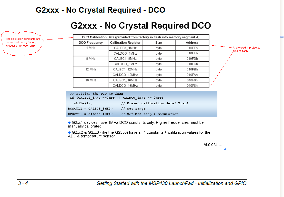
  BCSCTL1 = CALBC1_12MHZ; //Basic Clock System Control 1 = Index for BCSCTL1 Calibration Data for 1MHz
  DCOCTL = CALDCO_12MHZ; //DCO Clock Frequency Control = Index for DCOCTL Calibration Data for 1MHz
  
  BCSCTL2 = SELM_0 + DIVM_0 + DIVS_0; // DCO for Main and Subsytem CLK (w/o divider)
  
  P1DIR |= BIT4; //Sets CLK on P1.4 for measurement
  P1SEL |= BIT4;  
  
  while(1) i++; //dummy    
}

Results are:
for 1MHz I got 860kHz on my oscilloscope,
for 8MHz I got 444kHz,
for 12MHz I got 227kHz,
for 16MHz I got 113kHz.

I changed my chip for MSP430G2452 and repeated measurements - I got exactly what I set, even 16MHz.
What is wrong with my MSP430G2553? How to fix it?

  • sounds like the factory calibration points got corrupted, have you tired setting the bits manually in the DCO and BCS and seeing if the chip responds correctly.

    full blast, DCO on highest range with highest value is around 18.7MHZ  I think, play with the bit values and dial in the frequency you want and set the DCO and BCS values manually rahter than calling the factory "CALDCO_xxx" values

    if the chip responds correctly there should be a way to write values back into those slots in flash once you tune it in, but I don't know what it is, smarter people on here can steer you toward that if that is the issue

  • Hi bienieck & Joseph Woodrell,

    There is a code example that will generate new DCO calibration constants for you, provided that you have a 32768Hz crystal on XT1. It is called msp430g2xx3_dco_flashcal.c and you can find it in the G2553 code examples on the web or in MSP430ware.

    Basically what it does is that it uses the XT1 crystal as a reference frequency, and increments/decrements the DCOCTL/BCSCTL1 settings until it finds the setting that is best for each of the calibrated frequencies (1, 8, 12, 16MHz), then it writes these settings back in INFOA Flash in place of your corrupted settings. It's great for if you accidentally did an erase of the segment and lost your settings.

    Regards,

    Katie

  • Are you running your code with the JTAG Tool attached?

    If so, P1.4 is used as JTAG TCK, not showing SMCKL.

    Disconnect the JTAG cable and run your code standing alone.

  • Thank You Joseph. I set the BCS and DCO in MSP430G2553 just like they are set in MSP430G2452 and now frequencies are correct.

    Katie, I have MSP430G2452 chip as a reference, in a way. So it is posible to copy MSP430G2452 configuration values into MSP430G2553? In another words - were I can find Calibration Data?

  • I doubt that this is caused by bad calibration constant. You can examine the contents of 0x0FF8 to 0x0FFF to see them.

    See my earlier post for another possibility for the strange clock frequency.

    -- OCY

  • JTAG has nothing to do with it. MSP430G2452 works perfect.

  • old_cow_yellow said:

    I doubt that this is caused by bad calibration constant. You can examine the contents of 0x0FF8 to 0x0FFF to see them.

    See my earlier post for another possibility for the strange clock frequency.

    -- OCY

    Sorry, I gave the wrong address. The calibration constants are stored at the end of Into-A. The address is 0x10F8 to ox10FF.

    -- OCY

  • How to navigate on this memory? What is segment? In IAR I have: Memory, SFR, RAM, INFO and FLASH - which one is the correct one? I mean in which config data are stored? In "dco_flashcal.c" pointer points beginning of seg A and it is (in code) 0x10C0.

      Set_DCO(DELTA_1MHZ);                      // Set DCO and obtain constants
      CAL_DATA[j++] = DCOCTL;
      CAL_DATA[j++] = BCSCTL1;
    
      Flash_ptrA = (char *)0x10C0;              // Point to beginning of seg A
      FCTL2 = FWKEY + FSSEL0 + FN1;             // MCLK/3 for Flash Timing Generator
      FCTL1 = FWKEY + ERASE;                    // Set Erase bit
      FCTL3 = FWKEY + LOCKA;                    // Clear LOCK & LOCKA bits
      *Flash_ptrA = 0x00;                       // Dummy write to erase Flash seg A
      FCTL1 = FWKEY + WRT;                      // Set WRT bit for write operation
      Flash_ptrA = (char *)0x10F8;              // Point to beginning of cal consts
      for (j = 0; j < 8; j++)
        *Flash_ptrA++ = CAL_DATA[j];            // re-flash DCO calibration data
      FCTL1 = FWKEY;                            // Clear WRT bit
      FCTL3 = FWKEY + LOCKA + LOCK;             // Set LOCK & LOCKA bit

    OCY, where you find that info: "P1.4 is used as JTAG TCK"?

  • OCY, I checked your theory about JTAG and you were wrong.

    Now I restored all segment A to factory values, but there are still wrong results.

    I think the problem is in header file msp430g2553.h:

    /************************************************************
    * Calibration Data in Info Mem
    ************************************************************/
    
    /* TLV Calibration Data Structure */
    #define TAG_DCO_30             (0x01)    /* Tag for DCO30  Calibration Data */
    #define TAG_ADC10_1            (0x08)    /* Tag for ADC10_1 Calibration Data */
    #define TAG_EMPTY              (0xFE)    /* Tag for Empty Data Field in Calibration Data */
    
    #ifndef __DisableCalData
    #define TLV_CHECKSUM_          (0x10C0u)  /* TLV CHECK SUM */
    READ_ONLY DEFW( TLV_CHECKSUM      , TLV_CHECKSUM_)
    #define TLV_DCO_30_TAG_        (0x10F6u)  /* TLV TAG_DCO30 TAG */
    READ_ONLY DEFC( TLV_DCO_30_TAG    , TLV_DCO_30_TAG_)
    #define TLV_DCO_30_LEN_        (0x10F7u)  /* TLV TAG_DCO30 LEN */
    READ_ONLY DEFC( TLV_DCO_30_LEN    , TLV_DCO_30_LEN_)
    #define TLV_ADC10_1_TAG_       (0x10DAu)  /* TLV ADC10_1 TAG */
    READ_ONLY DEFC( TLV_ADC10_1_TAG   , TLV_ADC10_1_TAG_)
    #define TLV_ADC10_1_LEN_       (0x10DBu)  /* TLV ADC10_1 LEN */
    READ_ONLY DEFC( TLV_ADC10_1_LEN   , TLV_ADC10_1_LEN_)
    #endif
    
    #define CAL_ADC_25T85          (0x0007u)  /* Index for 2.5V/85Deg Cal. Value */
    #define CAL_ADC_25T30          (0x0006u)  /* Index for 2.5V/30Deg Cal. Value */
    #define CAL_ADC_25VREF_FACTOR  (0x0005u)  /* Index for 2.5V Ref. Factor */
    #define CAL_ADC_15T85          (0x0004u)  /* Index for 1.5V/85Deg Cal. Value */
    #define CAL_ADC_15T30          (0x0003u)  /* Index for 1.5V/30Deg Cal. Value */
    #define CAL_ADC_15VREF_FACTOR  (0x0002u)  /* Index for ADC 1.5V Ref. Factor */
    #define CAL_ADC_OFFSET         (0x0001u)  /* Index for ADC Offset */
    #define CAL_ADC_GAIN_FACTOR    (0x0000u)  /* Index for ADC Gain Factor */
    
    #define CAL_DCO_16MHZ          (0x0000u)  /* Index for DCOCTL  Calibration Data for 16MHz */
    #define CAL_BC1_16MHZ          (0x0001u)  /* Index for BCSCTL1 Calibration Data for 16MHz */
    #define CAL_DCO_12MHZ          (0x0002u)  /* Index for DCOCTL  Calibration Data for 12MHz */
    #define CAL_BC1_12MHZ          (0x0003u)  /* Index for BCSCTL1 Calibration Data for 12MHz */
    #define CAL_DCO_8MHZ           (0x0004u)  /* Index for DCOCTL  Calibration Data for 8MHz */
    #define CAL_BC1_8MHZ           (0x0005u)  /* Index for BCSCTL1 Calibration Data for 8MHz */
    #define CAL_DCO_1MHZ           (0x0006u)  /* Index for DCOCTL  Calibration Data for 1MHz */
    #define CAL_BC1_1MHZ           (0x0007u)  /* Index for BCSCTL1 Calibration Data for 1MHz */

    All my CAL_DCO's and CAL_BC1's are equal to index numbers, not values those indexes points in memory. How to fix it? Is it connected with __DisableCalData? 

    Another thing - I think header is not consistent with the documentation. In datasheet (page 15) are different offsets for config data and different tag number for ADC...

    In case someone will need factory values of FLASH (INFO memory: segment A - 0x10C0-0x10FF), here they go:

    0x20, 0x70, 0xFE, 0x16, 0xFF, 0xFF, 0xFF, 0xFF, 0xFF, 0xFF, 0xFF, 0xFF, 0xFF, 0xFF, 0xFF, 0xFF, 0xFF, 0xFF, 0xFF, 0xFF, 0xFF, 0xFF, 0xFF, 0xFF, 0xFF, 0xFF, 0x10, 0x10, 0xFD, 0x7F, 0x00, 0x00, 0x3A, 0x81, 0xF3, 0x02, 0x00, 0x00, 0xAA, 0x81, 0xC3, 0x01, 0x00, 0x00, 0xFE, 0x08, 0xFF, 0xFF, 0xFF, 0xFF, 0xFF, 0xFF, 0xFF, 0xFF, 0x01, 0x08, 0x93, 0x8F, 0x9B, 0x8E, 0x8F, 0x8D, 0xD4, 0x86

    And helpful information about that stuff: http://ares.ee.nchu.edu.tw/Course.files/epr100/lecture11.pdf (page 26 especially).

  • bienieck said:
    I think the problem is in header file msp430g2553.h:

    Unfortunately you do not show CALBC1_* and CALDCO_* defines.

    Anyway your factory calibration seems good. CALBC1_8MHZ = 0x8d and CALDCO_8MHZ = 0x8F.

    What you can do - try this:

    BCSCTL1 = 0x8d;
    DCOCTL = 0x8F;

    Mine g2553 have 8MHz factory constants 0x8D and 0x90 respectively giving 7.96 MHz, your constants on mine g2553 gives 7.94 MHz. Nothing close to 444 KHz :)

  • Ilmars said:
    Unfortunately you do not show CALBC1_* and CALDCO_* defines.

    Yes I did.

    Sure, DCO will work if I hard code factory constans, but I want BCSCTL1 = CALBC1_xMHZ and DCOCTL = CALDCO_xMHZ working properly with default library. Problem is, in my opinion, in header or compilator settings. But still, I don't now how to make it work.

  • bienieck said:

    Unfortunately you do not show CALBC1_* and CALDCO_* defines.

    Yes I did.

    [/quote]

    No. You did not. In your posts there's no #define for CALBC1_12MHZ or CALBC1_8MHZ. Just TLV structure definitions which BTW are absent in my msp430g2553.h file of IAR compiler.

    For instance I don't have any problems with v5.6 IAR. Your code with added  #include <msp430g2553.h> at the beginning compiled and worked as expected. I used default header files of compiler, there were no any .h in project directory.

  • Those definitions are in my post from Jan 04 2014 14:49 PM in code lines 32-39. There are no others definitions for that.

    Its weird that your header is different than my. Can you send me your library please?

  • The issue may be caused by the power voltage which is low than the requirement power level.  Please try to increase the power level.

    Properties Page -> Debug -> MSP430 properties -> [Target Voltage (mV)] = 3000

    Change 3000 to 3300 and try it again. 

  • bienieck said:
    Those definitions are in my post from Jan 04 2014 14:49 PM in code lines 32-39

    Line 32:

    #define CAL_DCO_16MHZ          (0x0000u)  /* Index for DCOCTL  Calibration Data for 16MHz */

    This is not CALBC1_16MHZ

    bienieck said:
    There are no others definitions for that.

    So if you managed to compile your code where CALBC1_12MHZ and CALDCO_12MHZ used then how it can be? Compiler would complain

    Here's calibration part of g2553.h:

    /************************************************************
    * Calibration Data in Info Mem
    ************************************************************/

    #ifndef __DisableCalData

    #define CALDCO_16MHZ_ (0x10F8u) /* DCOCTL Calibration Data for 16MHz */
    READ_ONLY DEFC( CALDCO_16MHZ , CALDCO_16MHZ_)
    #define CALBC1_16MHZ_ (0x10F9u) /* BCSCTL1 Calibration Data for 16MHz */
    READ_ONLY DEFC( CALBC1_16MHZ , CALBC1_16MHZ_)
    #define CALDCO_12MHZ_ (0x10FAu) /* DCOCTL Calibration Data for 12MHz */
    READ_ONLY DEFC( CALDCO_12MHZ , CALDCO_12MHZ_)
    #define CALBC1_12MHZ_ (0x10FBu) /* BCSCTL1 Calibration Data for 12MHz */
    READ_ONLY DEFC( CALBC1_12MHZ , CALBC1_12MHZ_)
    #define CALDCO_8MHZ_ (0x10FCu) /* DCOCTL Calibration Data for 8MHz */
    READ_ONLY DEFC( CALDCO_8MHZ , CALDCO_8MHZ_)
    #define CALBC1_8MHZ_ (0x10FDu) /* BCSCTL1 Calibration Data for 8MHz */
    READ_ONLY DEFC( CALBC1_8MHZ , CALBC1_8MHZ_)
    #define CALDCO_1MHZ_ (0x10FEu) /* DCOCTL Calibration Data for 1MHz */
    READ_ONLY DEFC( CALDCO_1MHZ , CALDCO_1MHZ_)
    #define CALBC1_1MHZ_ (0x10FFu) /* BCSCTL1 Calibration Data for 1MHz */
    READ_ONLY DEFC( CALBC1_1MHZ , CALBC1_1MHZ_)

    #endif /* #ifndef __DisableCalData */

    If you need whole file - you can download free IAR msp430 IDE, install it and you are done.


  • bienieck said:
    Katie, I have MSP430G2452 chip as a reference, in a way. So it is posible to copy MSP430G2452 configuration

    No. Each MSP (even two of the same model) require different calibration data. This is why it is calibration data, not generic constants.

    To restore them if lost, you have to recalibrate, that means compare the DCO speed to a known reference and adjust the DCO until they match and then store the resulting setting. This is what TI does at production time to determine the individual calibration data. (and if you spend more time than TI does, you might end up with more precise results than the original ones)

  • Hi bienieck,

    Jens-Michael is right, you cannot just copy factory calibration constants from another device. They are tested and programmed in per unit, so they will be slightly different on every device coming out of the factory. For an accurate set of DCO calibration constants you should use instead the code example that I mentioned above with a 32768 crystal on the board, to find new DCO cal constants specific for this particular device (or you could of course do it manually).

    bienieck said:
    Sure, DCO will work if I hard code factory constans, but I want BCSCTL1 = CALBC1_xMHZ and DCOCTL = CALDCO_xMHZ working properly with default library. Problem is, in my opinion, in header or compilator settings. But still, I don't now how to make it work.

    For this issue, please see this thread: http://e2e.ti.com/support/microcontrollers/msp430/f/166/p/310476/1089128.aspx#1089128

    Your problem may have been caused by a recent update in CCS of the header files, but these have now been reverted - if you already had the update applied you would need to re-install CCS, or if you don't want to do that I've provided the corrected files for MSP430G2553 in the post I linked above - you can just replace the files in CCS with these versions.

    Regards,

    Katie

**Attention** This is a public forum