This thread has been locked.

If you have a related question, please click the "Ask a related question" button in the top right corner. The newly created question will be automatically linked to this question.

MSP430F5436A BSL issue

Other Parts Discussed in Thread: MSP430F5436A

Hi , 

I encounter an issue when I programming Flash of MSP430F5436A using UART interface.

The document said only these pins are required: RST, TEST, P1.1 , P1.2 , Vcc , Vss.

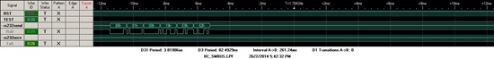
I followed  the signal sequence set TST, TEST, and send 0x80 to MCU, but did not get any response from MCU.

Is there any one can help take a look the signal, or give suggestion ?

Thanks !

Qijie  


  • Hi Leo Hendrawan,

    Thank you reply this question, my problem is different from that. On my board, I could not get any response from MCU even 0x00.  

    Any suggestion ?

    Thanks  & Regards,

    qijie    

  • Qijie,

    you need to send a whole packet instead only of single sync byte 0x80 to the MSP430x5xx BSL. 

    Please refer for example to www.ti.com/lit/slau319 chapter 3.7.4 Example Sequences for UART BSL

  • Hi Leo Hendrawan,

    I also tried to send the whole  packet by using BSL scripter, no response.

    I tested three boards, include one MSP430-Experiment board(F5438A).

    Thanks  & Regards  

    qijie   

  • Hi qijie,

    Are you trying to communicate from a PC to the MSP430? What hardware are you using to interface the PC COM port to the MSP430 pins? (e.g. TUSB chip, FTDI chip, etc).

    Please note that if you simply plugged into the mini-USB port of the MSP-EXP40F5438A board, this goes through a TUSB chip on the board that does not support the parity that is used by the BSL, so it won't work (I also think this is connected to different pins on the part than the BSL pins as well).

    The BSL requires even parity and 9600 baud, so you need to make sure that however you are using to interface between the PC and the MSP430 is set up for this configuration. For testing, one known solution you can try out if you have an MSP-EXP430G2 launchpad handy is to use that as your BSL interface, using the app note that Leo wrote: www.ti.com/lit/pdf/slaa535

    Regards,

    Katie

  • Hi Kaite,

    I do not think the  communication between PC and MSP430 has problem. I verified the communication by jumping to 0x1000 from my application, and got the response.

    So I think IT should there is limitation about  RST and TEST pin signal sequence I did not realized.

    Later I checked MSP430F5436A Device Erratasheet, slaz286j.pdf.  In page22, it said "

    The BSL entry sequence requires that the low phase of the TEST/SBWTCK pin does not
    exceed 15us. This timing requirement is faster than most PC serial ports can provide, as
    shown in the following picture. If this requirement is not met, the entry sequence fails
    and the SYSBSLIND is not set"

     Is it the reason MCU did not enter BSL mode?  Does  MSP-EXP430G2 launchpad meet such requirement?  

    I did another test today.

    I still use RST and TEST pin. but on TEST pin, the signal acts on it is TCK 's signal. just like figure 1-3 of slau319g.pdf. It surprised me that  the MCU enter BSL mode!

    I double checked PCB , RST is connected to MCU pin96, TEST  is connected to MCU pin91. The PCB connection no issue.

    But I did not find any spec introduce such method enter BSL mode. May I know if it is a safe way ? I do not want to  prepare another HW to satisfy  "<15 us " condition.

    Thanks and Regards,

    qijie  


  • qijie,

    it might be the problem. If you have a D/E/G die revision, it is affected by SYS10 bug which require very short pulse (<15 us) at the TEST pin to generate BSL.

    The solution which i pointed out before with the Launchpad (SLAA535) takes this into account and generate TEST pulses with <15 us.

  • Hi Leo Hendrawan, 

    The chip  we are using are REV D and REV G. 

    It is confirmed when negative pulse width <15us, MCU enters BSL mode. thanks.

    One more thing, when asking version number , MCU answer with "00 80 02 00 3B 04 E4 84", the BSL _scripter does not understand this format. Could you tell is it standard TI BSL ? If not, how can I get TI BSL ?   


    Thanks & Regards,

    qijie           

  • Hi,

    if you refer to the BSL user's guide, the message can be interpreted as follows:

    80 : header (see chapter 3.2.1 "Wrapper")

    02 00 : length (2 bytes) (see chapter 3.2.1 "Wrapper")

    3B: MSG: (see chapter 3.7 "BSL Core Responses")

    04: BSL locked ((see chapter 3.7.2. "BSL Core Messages")

    E4 84: checksum (see chapter 3.2.1 "Wrapper")

**Attention** This is a public forum