This thread has been locked.

If you have a related question, please click the "Ask a related question" button in the top right corner. The newly created question will be automatically linked to this question.

MSP430F4132 BSL loading issues

Other Parts Discussed in Thread: MSP430F4132, MSP430F1121, TEST2, MSP-TS430PM64A, MAX3221, TUSB3410, MSP430F1612, MSP430F5529

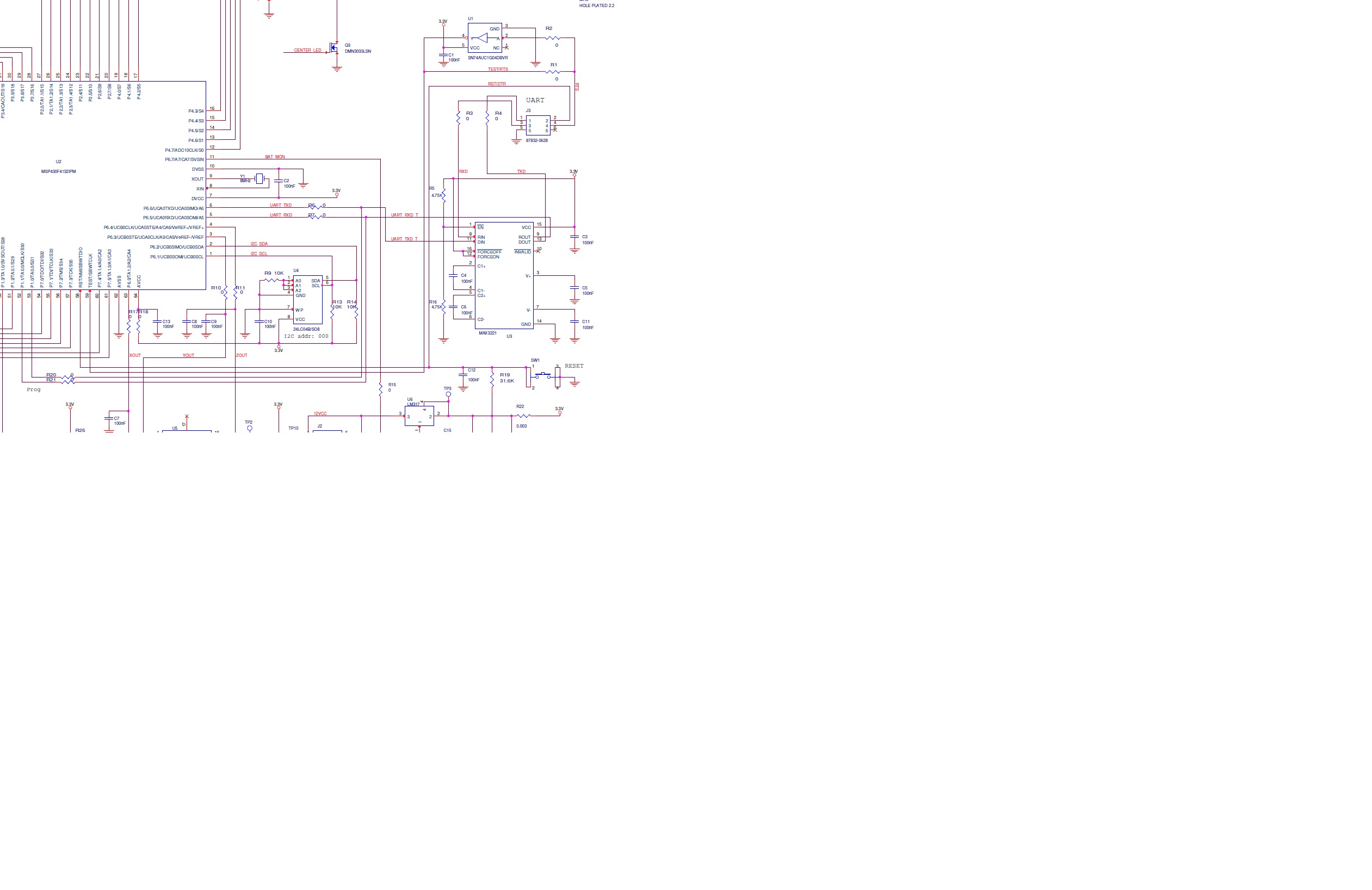
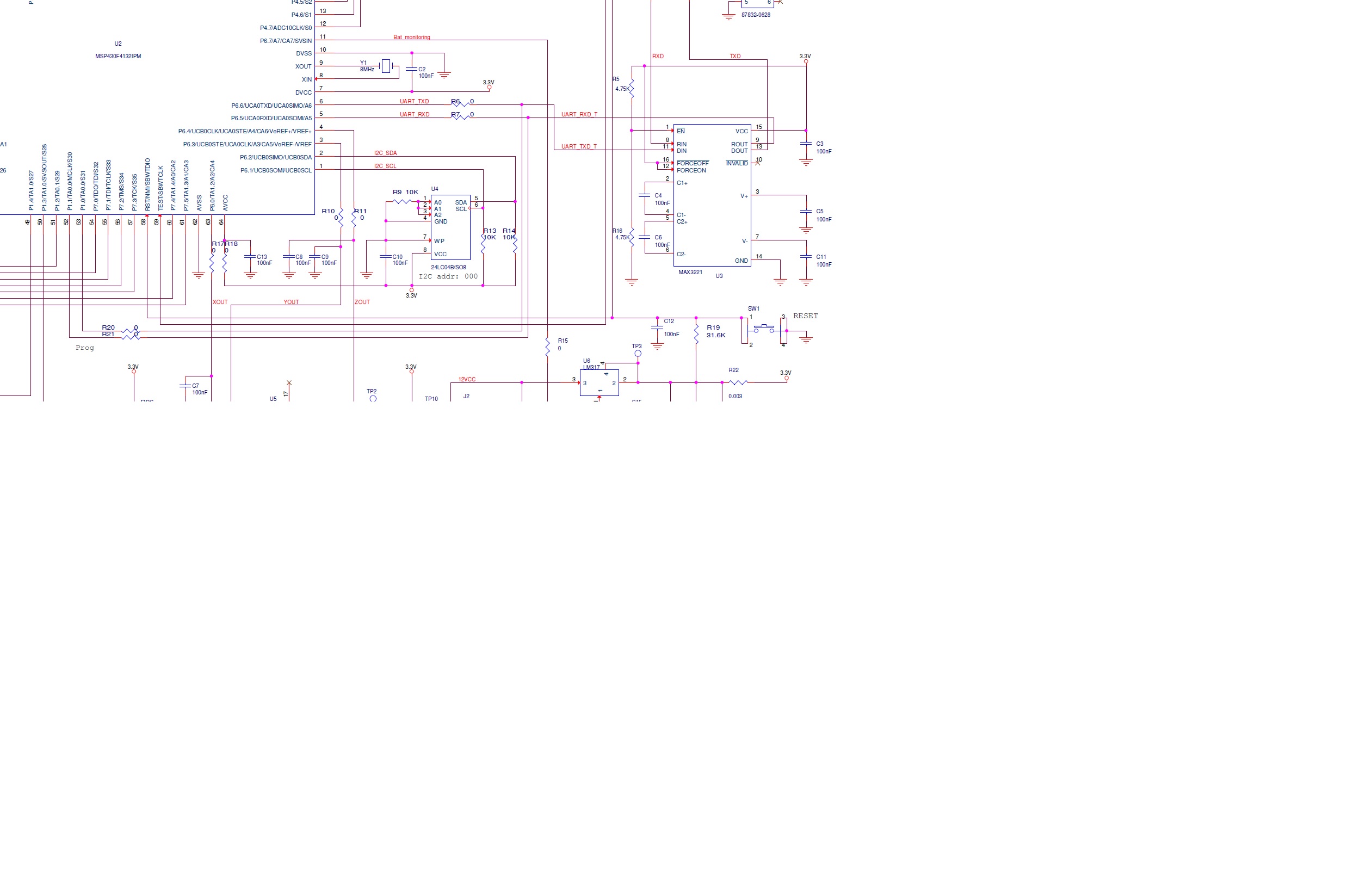
Hello,  I am having issues loading the bootloader code into MSP430F4132.

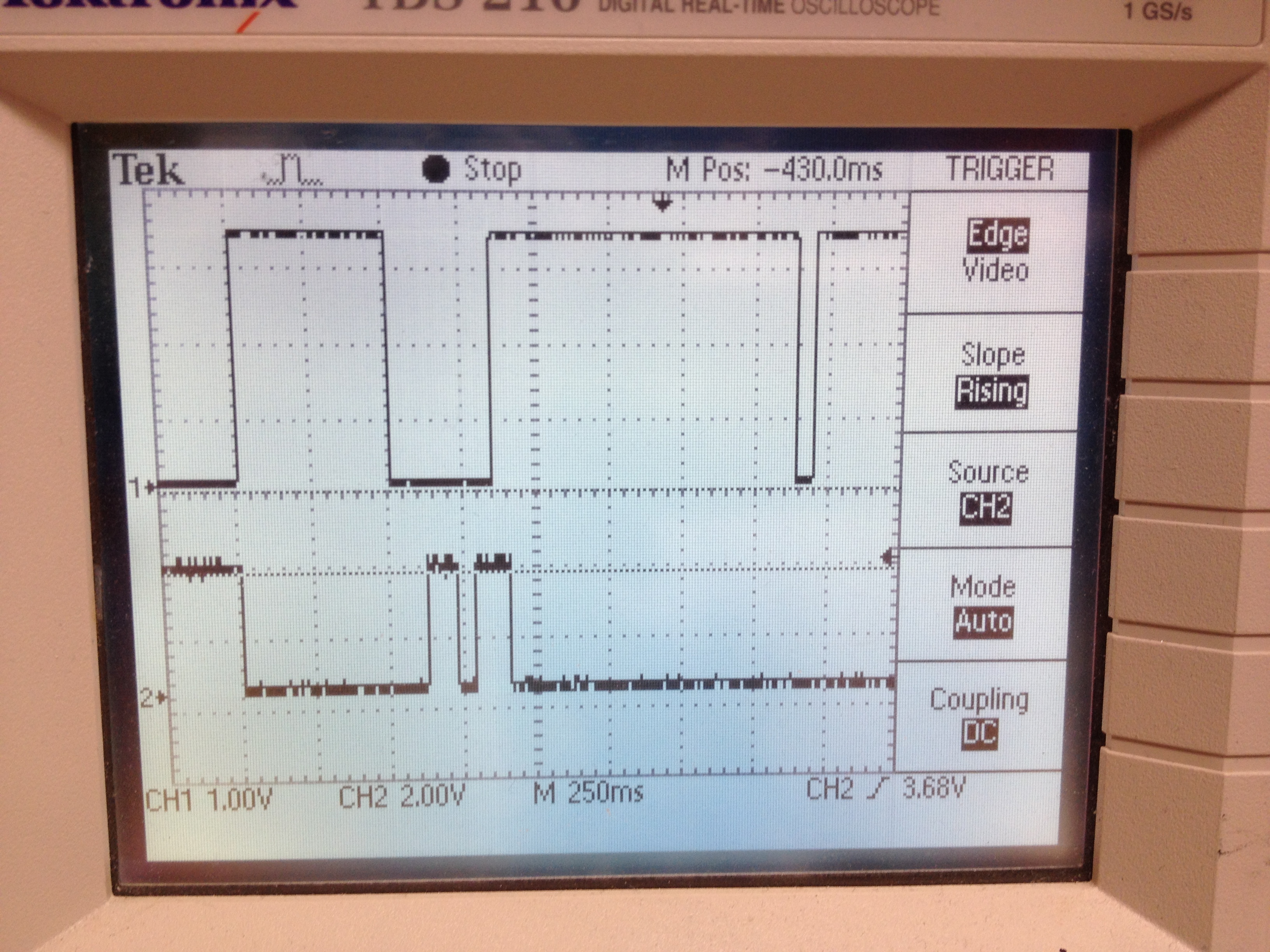
The TEST/RST patterns shown in SLAU319g document are right on and it appear the MC is responding on RXD line but the answer is that the synchronization failed. so I'm stuck

The questions are:

- Is this MC using the TEST or the TCK signal as the document is confusing regarding devices with shared TEST or TCK versus dedicated pins.

- Are there various versions of bootloaders for different devices? I am using version 1.30 which is what I could find although table 5.5 says I should be using version 1.61. Version 1.30 worked with an F1121 MC on an earlier project. If so where do I download various versions of the bootloader SW?

all connections are per datasheet with RXD to P1.1 and TXD to P1.0, using TEST inverted and RST. The same setup worked fine with MSP430F1121

Anybody had issues with this 430F4132 MC bootstrap?

Thanks a lot!

  • Furthermore, which scripter should I be using: the BSL_scripter.exe or the BSLdemo2.exe. I have been using BSLDEMO2.exe. Maybe that is the problem..

    Thanks,

  • The answer is simple: if an MSP does not have a TEST pin, it obviously cannot be used for the BSL entry sequence. In this case (and only in this case), the functionality is wired to the TCK pin (which in this case is a dedicated JTAG pin and not multiplexed with GPIO).

  • Thank you Jean-Michael.. so just to be clear, for this particular device, MSP430F4132, even though I have a shared functionality TEST pin and another shared functionality TCK, I should be using the TCK pin and NOT the TEST pin.

    On a separate note, the TCK pin shares functionality with P7.3 on this device so I'm not sure if I read your response right.

    Because I tried with TCK (non inverted)with no success. It could be that I was using the wrong scripter as I was using the BSLDEMO2 instead of the BSL_Scripter? I am confused about which one I should be using.

    Thanks,

    Nick

  • Hi Nick,

    I think you may have misunderstood what Jens-Michael was saying. It is simply this: if the device has a TEST pin on it at all, use the TEST pin (not TCK). If there is no TEST pin at all on the device, that is the only time you should use TCK. So since your F4132 has TEST, you should use TEST (not TCK).

    What hardware are you using to interface between the PC and the MSP430 device? Is it the Launchpad BSL interface from www.ti.com/lit/pdf/slaa535, or something else?

    Also I can confirm that 4xx devices are supported by BSLDEMO2 - that is the correct software to use. The BSL_Scripter is only for F5xx/6xx/FR5xx devices.

    Regards,

    Katie

  • Hello Katie, thank you for replying. OK so I'm now clear with TEST vs TCK. However, still confused with the scripter. This is an MSP430F4132 (Fxxx) device not Fxx. Do I still use the BSLDEMO2? or do I have to use an updated one that recognizes the family?

    I can't find any reference anywhere about which one should be used with Fxxx devices.

    As for what I use to program for hardware I have built the circuit that is referenced as HW in SLAU319G document and using a scope I can confirm that I am sending the correct pattern on TEST and RESET lines. I also get one or two pulses back in RXD when this happens but still I get the non sync error.

    The same circuit along with BSLDEMO2 software has successfully programmed another project using MSP430F1121 so I know the hardware used for programming works.

    Hence the question of whether I'm using the correct software or not.

  • Hi Nick,

    BSLDEMO2 is the correct software to use for the F4132 device.

    Nick Petrescu said:

    This is an MSP430F4132 (Fxxx) device not Fxx. Do I still use the BSLDEMO2? or do I have to use an updated one that recognizes the family?

    I can't find any reference anywhere about which one should be used with Fxxx devices.

    This is a terminology confusion - sorry about the mixup. When we say F4xx, we mean all devices that start with an F4, no matter how many digits are after the 4. So I was including F4132 in my earlier statement. You can see this in documents like the user's guide for your device, which is called the MSP430x4xx user's guide but it covers all of the parts from the F417 to the F4132 to the F47179 - all parts that start with a 4.

    Could you post the batch file or command line commands/parameters that you are using to try to run the BSLDEMO2.exe? Maybe there is something that is not set quite right. I will also try to find a part that has the same BSL version as the F4132 to test with.

    In addition, are you using a TI target socket board, or your own design, and what connections do you use for example for Vcc etc between your BSL HW and your MSP430 board? Are you powering your board from the BSL tool or powering it externally, and which Vcc pin is used on the BSL HW?

    Regards,

    Katie

  • Hi Katie,

    Thank you so much for the quick response.

    - I am using my own design. It is pretty simple, based on the reference design posted on TI site. nothing fancy.

    - The design is powered by its own power supply 3.3V. The BSL tool is powered by its own power supply. The two boards share the GND, TXD, TEST/DTR and RST.NMI signals. TEST is inverted as per SLAU319G.

    scope shots- which I can send I necessary show the correct BSL sequence at the MSP430 pins. All voltage levels are correct. (as said I used this setup with an older F1121 device successfully so I'm really suspecting the SW at this point.

    - TXD seem to blip one or two pulses- I will confirm later- so the processor is clearly alive yet I get the no sync error

    below is my batch file:

    @echo off
    rem ---- initialize environment variables -----------------------------

    setlocal
    set workdir=%CD%

    set HANDLER="%workdir%\bsldemo2.exe"
    set BSL="%workdir%\bsl_150.txt"
    set BSL130="%workdir%\BL_130V.txt"
    set BSL150="%workdir%\BL_150S_14x.txt"
    set TXT="%workdir%\nick_4132.txt"
    set ComPort=COM6
     
    goto test1


    :test1
    echo --- test F413 (V1.30), F123 (V1.40), both 1 mass erase cycle ----
    echo.
    %HANDLER% -c%ComPort% -m1 -s0 +epvw  %TXT%
    goto end


    :test2
    %HANDLER% -c%ComPort% +pvrw     %TXT%
    %HANDLER% -c%ComPort% -w        %TXT%
    %HANDLER% -c%ComPort% -s2 -w    %TXT%
    %HANDLER% -c%ComPort% -w +vr  -pint_vect.txt %TXT%
    goto end


    rem ---- clear environment variables ---------------------------------
    :end
    pause
    set HANDLER=
    set BSL=
    set BSL130=
    set BSL150=
    set TXT=
    set ComPort=

    .

  • Hello Katie, I think you may be right... I believe I'm using the wrong BSL file which is not compatible with my device. Would you be able to help with a link or a file that is compatible with F4132? Acoording to SLAU319g that would be version 1.61 or later. Thank you so much!

  • Hi Nick,

    Here is my known working setup that I just tried with an F4152 device on the MSP-TS430PM64A target board:

    I used the Launchpad BSL interface from www.ti.com/lit/pdf/slaa535 as my hardware - if you have access to an MSP-EXP430G2 Launchpad this would be great because we could try the exact same setup. I supplied my target board from the Launchpad.

    First, load the SLAA535 code into the Launchpad: www.ti.com/lit/zip/slaa535

    I make these connections:

    Launchpad F4152
    Vcc Vcc
    Gnd Gnd
    P1.4 RST
    P1.5 TEST
    P1.6 P1.0 (BSL TX)
    P1.7 P1.1 (BSL RX)

    Then, I connect the Launchpad to the PC. You should see both Launchpad LEDs turn on and stay on (no blinking) - this means the entry sequence was successful. Then I ran the batch file in this attached folder: 4024.BSLDEMO2_tests.zip

    And it correctly loaded the part with the TI-txt file I had in the folder. The batch file is super simple - it just calls:

    BSLDEMO2.exe -cCOM16 -m1 +epvrw msp430x41x2_1.txt

    (Of course you will need to change the COM port to match whatever your Launchpad enumerates on).

    This was all using the BSLDEMO2.exe that came from SLAU319g, so you have the right software. So if you have a Launchpad handy you could follow these steps and see if it works for you - it may be your hardware that is the issue.

    Regards,

    Katie

  • Thank you so much Katie. I have a feeling hat the txt file you included will do the trick because I know I was using the wrong one for a F1121 device. I will report with the results for the TI MC community benefit.

    Nick

  • Hi Katie,

    it looks I'm out of luck. I get the same error using the files you sent. However it appears that my sequence is correct. I have scope shots I can send along if someone can  take a look at them.

    It appears that as soon as the TEST sequence ends, the processor responds on TXD with a 1s high pulse, then TEST responds with another low pulse then high again. Does someone have a waveform that shows what happens after the processor has accepted or not accepted the entry sequence? How is it supposed to respond? on TXD, how many pulses etc.

    I know my schematic is correct. I am feeding TXD and RXD thru a known working reference schematic which is on board using MAX3221 Chip to achieve TTL 3.3V levels. The TEST and RST signals are fed thru triple and respectively double inverters using the SLAU319g suggested hardware schematic so I can't see what I may be doing wrong unless somehow the processors have gotten bad bot on the other hand, the fact that it does respodn to the sequence on TXD sort of proves it is still alive.

    Nick

  • Hi Nick,

    Do you have any application code running on the device (i.e. LED toggle)? Does the application start after the entry sequence?

    Please send us the screenshots if you can, including TEST, RESET, TXD and RXD.

    I don't think the MCU will toggle the TEST pin since this is an input for the MSP430. Is your host driving the pin actively or is it floating after the entry sequence?

    TXD will be set as output high instead of Hi-Z input (default state after reset), but the device won't respond or toggle the pin, unless it detects something on RXD.

    Is RXD set as output high by the Host circuitry? 

    Regards,

    Luis R

  • Hello Luis,

    - I am only running the batch file that Katie sent. Essentially the BSL file. No application yet.

    - screenshots attached. First one is the TEST(CH2) and RST(CH1) sequence. The second is the TXD(ch2) vs TEST(ch1) sequence showing that the processor responds via TXD after sending the BSL sequence. I did not say the MCU toggles the TEST but the TXD rather. TXD is an output from MCU. It is true that there was no pulse on RXD at all at all this time. Schematic attached. Note that R1 is not populated in the schematic and both TEST and RST signals are fed from an USB to RS232 cable via a double set of 7V tolerant inverters circuit that is powered separately by a 3.3V supply. the schematic and this circuit share the ground.

    Thank you,

    Nick

    - I am only using the batch file and text file BSL that Katie sent above. I

    -

  • Hi Nick,

    Thank you for the update. 

    The only problem I see in the screenshots is that glitch on RST. What is causing that? Does the same happen if you try checking the output from USB->RS232 disconnected from MSP430?

    Now, I ran some tests using the circuitry found in SLAU319 and got the following:

    - Good entry sequence. Note that the entry sequence is similar to yours and TXD is pulled high as soon as the MSP430 goes to BSL (just like your case), but the host sends the first packet after ~260ms.

    - Then I tried disconnecting RXD/TXD from MSP430. So the MSP430 detects the entry sequence but the host doesn't detect the device:

    Same happens if I connect RXD, so the MSP430 detects the host but the host doesn't receives the response from MSP430:

    This seems to indicate to me that your host is not receiving a response from MSP430, but I'm not sure if the MSP430 is receiving the ACK from the host.

    If you are not seeing anything on RXD, it could mean that this circuitry is not working. 

    Have you tried sending data to the MSP430 using Teraterm/Hyperterminal? Just to make sure that the circuitry works fine? If the device is blank, the TXD/RXD pins should be inputs after reset and you should be able to send data from host to the MSP430. 

    Looking at your circuitry, you seem to have a voltage divider for the EN pin, is that correct?

    Regards,

    LR

  • Ahh! of course... I've provisioned for both options and stuffed them both too by mistake. That pretty much disables my TX/RX RS232 chip as you've correctly pointed. I've ordered the Launchpad tool too and I will try tonight first removing the pull-up resistor which pretty much should make it work. If not the Launchpad should do it. Thank you so much for the waveforms. I think they are very valuable to all MSP430 community as it is not well documented in the existing TI docs. I'll let you know!

  • The MAX3221 enable was indeed the problem for initiating the sync, thank you so much. But no I get this error message:

    _boot>BSLDEMO2.exe -cCOM6 -m1 +epvrw msp430x41x2_1.txt
    MSP430 Bootstrap Loader Communication Program (Version 2.01)
    Number of mass erase cycles set to 1.
    Mass Erase...
    Transmit standard password...
    BSL version: 1.61 - Family member: 4152 - Process: 00B0
    Program "msp430x41x2_1.txt"...
    Program starting at c000, 184 bytes... Error: 7
    ERROR: Verification failed!
    ----------------------------------------------------------- Press any key ...

    Any idea what error 7 means?

    Thanks,

    Nick

  • Noticed it says family member 4152 but my MC is F4132IPMR. Is it possible that I have the wrong BSL file or containing the wrong ID although according to the SLAU319G 4152 and 4132 should have the same chip ID..

  • Hi Nick,

    The command is failing and the target device is returning a NAK.

    Are you still programming a F4132? If so, the program starts at 0xE000, not 0xC000. Maybe the msp430x41x2_1.txt file was built for F4152?


    Regards,

    Luis R

  • Try this file

    8117.Example.txt
    @E000
    31 40 00 04 B0 12 0C E0 B0 12 40 E0 B2 40 80 5A
    20 01 E2 D3 32 00 E2 E3 31 00 00 3C 3F 40 33 82
    3F 53 FE 2F F8 3F 0A 12 21 83 0A 4C 81 4A 00 00
    0D 41 0D 53 5C 43 B0 12 44 E0 F8 3F 30 40 26 E0
    30 40 3C E0 30 41 
    @FFFE
    00 E0 
    q
    

    LR

  • It appears that the latest file works. what was the change, just for my own knowledge?

    SLDEMO2_tests\BSLDEMO2_tests\Exe>BSLDEMO2.exe -cCOM6 -m1 +epvrw 4132.txt
    MSP430 Bootstrap Loader Communication Program (Version 2.01)
    Number of mass erase cycles set to 1.
    Mass Erase...
    Transmit standard password...
    BSL version: 1.61 - Family member: 4152 - Process: 00B0
    Program "4132.txt"...
    Program starting at e000, 70 bytes... Error: 0
    Program starting at fffe, 2 bytes... Error: 0
    72 bytes programmed.
    Verify... already done during programming.
    Programming completed.Prog/Verify: 0.1 sec - Over all: 0.6 sec
    ----------------------------------------------------------- Press any key ...

    Thank you so much for your help!!!

    Nick

  • The previous file was built for a F4152:

    Program starting at c000, 184 bytes... Error: 7

    Instead of a F4132:

    Program starting at e000, 70 bytes... Error: 0


    F4132 has a smaller flash and doesn't implement 0xC000. 


    I'm glad you have it working now. Good luck with the rest of your project.


    Regards,

    Luis R

  • Hello,

    I have decided to change my design to incorporate an USB to UART chip and I ordered the
    Launchapd MSP-EXP430G2 and planning to use the reference schematic that incorporates the TUSB3410VF chip.
    In order to verify it will work I have connected the two boards in the following fashion:

    soldered wires directly to the TUSB4130 chip on Launchpad board and ran them over to my board MSP430F4132 chip as follows:


    TUSB3410VF - MSP430F4132
    TXD pin 17 - P1.0 pin 53 and P6.6 pin 6
    RXD pin 19 - P1.1 pin 52 and P6.5 pin 5
    DTR pin 21 - RST pin 58
    RTS pin 20 - TEST  pin 59 via an inverter already placed on my board
    GND - GND

    VCC on launchpad via USB- VCC on MSPF430F4132 via my own power adapter delivering 3.3V

    I have loaded the drivers and the Launchpad shows as COM17
    I have loaded a terminal program and configured as baud 2400, 1 stop bit noflowctrl

    I have checked the 12MHz clock on X1 and its there.
    I have placed the scope on TXD , RXD pins on TUSB3410 and tried entering some keyboard characters and I get nothing. Also tried to run my BSL sequence and the DTR and RTS pins don't show anything
    However If I place the scope on J3 RXD and can see it is active so cleary the chip is working.

    I tried scoping the pins even with nothing connected to them and still nothing, yet I get the RXD signal blipping.

    Questions:

    1. Am I missing something? Why can't I use the outputs from TUSB3410 as described above to program my MSP430?

    2. Do I need to configure anything on TUSB3410 to make it work just with the Windows UART driver?

    3. Is there a generic Windows driver available from TI that enables me to use this chip as a USB to UART?
    4. it looks like I need to include the I2C E2PROM for the TUSB3410 to boot in my design, correct? Is there a generic binary file available and how do I load it? Do I need a programmer for that? 

    Thank you in advance for your help

    Nick

  • Nick Petrescu said:
    I have decided to change my design to incorporate an USB to UART chip and I ordered the Launchapd MSP-EXP430G2 and planning to use the reference schematic that incorporates the TUSB3410VF chip.

    Be sure you do not use the LaunchPad as reference design. The TUSB on the LaunchPad uses a special firmware to provide two separate serial connections, one (full speed hardware UART) to the MSP430F1612 FET and one (software UART, limited to 9600Bd) as a convenience channel to the MSP430 target processor.
    The standard firmware for the TUSB only uses the high-speed hardware UART .

    The COM port that appears in the device manager is just the slow software UART, simulated on two I/O pins of the TUSB.

    Due to the special firmware, the TUSB on the LaunchPad doesn’t enumerate on Windows as TUSB chip. It shows a different device ID and loads a different driver than the default one.
    The special firmware is loaded from the I2C EEPROM. If the EEPROM is not present or contains an invalid firmware (CRC error), then a generic USB boot code fetches the firmware form the Windows driver through USB.  So you don’t need the EEPROM if you want to run the TUSB as a generic USB->serial bridge. (at least that’s what I heard)

     Besides this, the BSL doesn’t use the hardware USCI module on the MSP. Instead, it uses a timer to implement an UART in software. It self-adjusts to the SYNC character, so timing is independent of the exact DCO clock speed (while the hardware UART requires a precise clock source). In case of the G2553, RX and TX for UART and BSL usage are twisted IIRC.

  • Yeah, sort of figured that I would need a custom EEPROM load to test my variant. I think it is just easier and cheaper overall to switch to another MCU that has USB and I have selected the MSP430F5529. I just ordered the Launchpad board based on that chip to test.

**Attention** This is a public forum