This thread has been locked.

If you have a related question, please click the "Ask a related question" button in the top right corner. The newly created question will be automatically linked to this question.

MSP430F5529 I2C Example Issues

Other Parts Discussed in Thread: MSP430F5529

I have tried the sample code for the MSP430F5529 with teh change to have it working on B1 as opposed to B0. I have posted the code below in its charged form. The issue I am getting is there does not appear to be any intelligent output from the I2C module, I have included a logic capture below. 

#include <msp430.h>

unsigned char *PTxData;                     // Pointer to TX data
unsigned char TXByteCtr;

const unsigned char TxData[] =              // Table of data to transmit
{
  0x11,
  0x22,
  0x33,
  0x44,
  0x55
};

int main(void)
{
  unsigned int i;

  WDTCTL = WDTPW + WDTHOLD;                 // Stop WDT
  P4SEL |= 0x06;                            // Assign I2C pins to USCI_B0
  UCB1CTL1 |= UCSWRST;                      // Enable SW reset
  UCB1CTL0 = UCMST + UCMODE_3 + UCSYNC;     // I2C Master, synchronous mode
  UCB1CTL1 = UCSSEL_2 + UCSWRST;            // Use SMCLK, keep SW reset
  UCB1BR0 = 12;                             // fSCL = SMCLK/12 = ~100kHz
  UCB1BR1 = 0;
  UCB1I2CSA = 0x48;                         // Slave Address is 048h
  UCB1CTL1 &= ~UCSWRST;                     // Clear SW reset, resume operation
  UCB1IE |= UCTXIE;                         // Enable TX interrupt

  while (1)
  {
    for(i=0;i<10;i++);                      // Delay required between transaction
    PTxData = (unsigned char *)TxData;      // TX array start address
                                            // Place breakpoint here to see each
                                            // transmit operation.
    TXByteCtr = sizeof TxData;              // Load TX byte counter

    UCB1CTL1 |= UCTR + UCTXSTT;             // I2C TX, start condition
    
    __bis_SR_register(LPM0_bits + GIE);     // Enter LPM0, enable interrupts
    __no_operation();                       // Remain in LPM0 until all data
                                            // is TX'd
    while (UCB1CTL1 & UCTXSTP);             // Ensure stop condition got sent
  }
}

//------------------------------------------------------------------------------
// The USCIAB0TX_ISR is structured such that it can be used to transmit any
// number of bytes by pre-loading TXByteCtr with the byte count. Also, TXData
// points to the next byte to transmit.
//------------------------------------------------------------------------------
#if defined(__TI_COMPILER_VERSION__) || defined(__IAR_SYSTEMS_ICC__)
#pragma vector = USCI_B1_VECTOR
__interrupt void USCI_B1_ISR(void)
#elif defined(__GNUC__)
void __attribute__ ((interrupt(USCI_B1_VECTOR))) USCI_B1_ISR (void)
#else
#error Compiler not supported!
#endif
{
  switch(__even_in_range(UCB1IV,12))
  {
  case  0: break;                           // Vector  0: No interrupts
  case  2: break;                           // Vector  2: ALIFG
  case  4: break;                           // Vector  4: NACKIFG
  case  6: break;                           // Vector  6: STTIFG
  case  8: break;                           // Vector  8: STPIFG
  case 10: break;                           // Vector 10: RXIFG
  case 12:                                  // Vector 12: TXIFG  
    if (TXByteCtr)                          // Check TX byte counter
    {
      UCB1TXBUF = 0x0C;//*PTxData++;               // Load TX buffer
      TXByteCtr--;                          // Decrement TX byte counter
    }
    else
    {
      UCB1CTL1 |= UCTXSTP;                  // I2C stop condition
      UCB1IFG &= ~UCTXIFG;                  // Clear USCI_B0 TX int flag
      __bic_SR_register_on_exit(LPM0_bits); // Exit LPM0
    }
  default: break;
  }
}

I have also tried my own code which is below also which I can not get working. Any help would be much appreciated.

#include <msp430f5529.h>

int initI2C(){
    P4SEL |= 0X60;
    UCB1CTL1 = UCSWRST;
    UCB1CTL0 = UCMST + UCMODE_3 +UCSYNC;
    UCB1CTL1 = UCSSEL_2 + UCSWRST; 
    UCB1BR0 = 12;                               //fSCL = SMCLK/12 = ~100kHz
    UCB1BR1 = 0;    
}

int sendI2C(){
    UCB1I2CSA = 0x60;                           //Set Slave Address 
    UCB1CTL1 &= ~UCSWRST;                     // Clear SW reset, resume operation
    // UCB1IE |= UCTXIE;                         // Enable TX interrupt
    UCB1CTL1 |= UCTR + UCTXSTT;             // I2C TX, start condition
    UCB1TXBUF = 0x0C
}

int main(){
    WDTCTL = WDTPW + WDTHOLD;                 // Stop WDT
    initI2C();
    sendI2C();
}

//------------------------------------------------------------------------------
// The USCIAB0TX_ISR is structured such that it can be used to transmit any
// number of bytes by pre-loading TXByteCtr with the byte count. Also, TXData
// points to the next byte to transmit.
//------------------------------------------------------------------------------
__interrupt void USCI_B1_ISR(void){
  switch(__even_in_range(UCB1IV,12))
  {
  case  0: break;                           // Vector  0: No interrupts
  case  2: break;                           // Vector  2: ALIFG
  case  4: break;                           // Vector  4: NACKIFG
  case  6: break;                           // Vector  6: STTIFG
  case  8: break;                           // Vector  8: STPIFG
  case 10: break;                           // Vector 10: RXIFG
  case 12:                                  // Vector 12: TXIFG  
    UCB1TXBUF = 0xC0;                   // Load TX buffer
    UCB1CTL1 |= UCTXSTP;                  // I2C stop condition
    UCB1IFG &= ~UCTXIFG;                  // Clear USCI_B0 TX int flag
    __bic_SR_register_on_exit(LPM0_bits); // Exit LPM0
  default: break;
  }
}

Thanks

  • Just to check, do you have appropriate pull-up resistors on the I2C bus lines?

  • Hello Robert, 

    I am using the XTRINSIC-SENSE-BOARD from Freescale and from the schematics I see there are pull-up resistors.


    Thanks for the suggestion though.

    Kas

  • Both codes look good (well, the second is only a stub, but should produce at least a valid start byte).

    So it seems to be a hardware problem. The analyzer graph seems to show an open high-impedance signal that generates spikes. You say the external pull-ups are in place. And is there a GND connection between master and slave?
    It would be interesting to see what a scope produces (the real waveforms on the pins, not the interpreted logic levels).

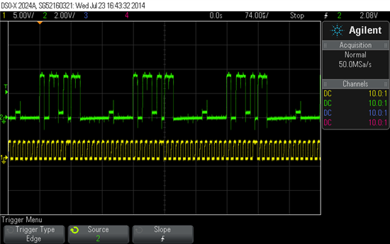
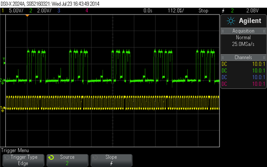
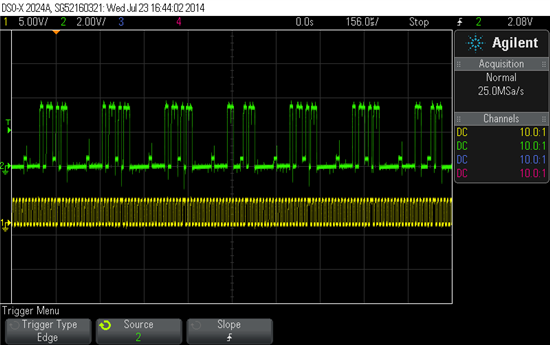
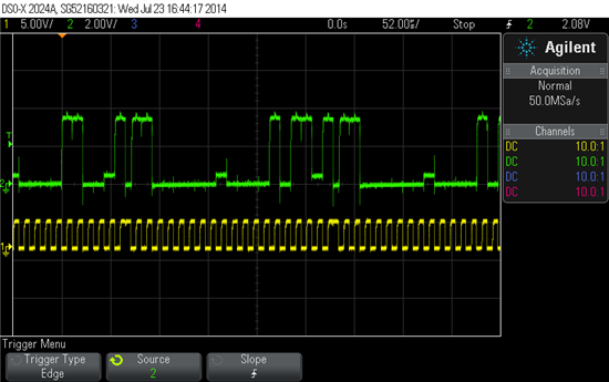
  • I have redone the test with the logic analyzer and a probe they look similar and correct (not sure what was going on before). That being said I still can't get the module to send a sequence I want it to, I will attach pictures of the output and of the code.

    The logic analyzer traces are consecutive basically one long trace cut in three.

      This is the first part of the trace

      This is the second part of the trace

      This is the third part of the trace

    The Scope traces are randomly grabbed as it is not possible to get one long and useful trace.

    Here is the code I am running 

    #include <msp430.h>
    
    unsigned char *PTxData;                     // Pointer to TX data
    unsigned char TXByteCtr;
    
    const unsigned char TxData[] =              // Table of data to transmit
    {
      0x11,
      0x22,
      0x33,
      0x44,
      0x55
    };
    
    int main(void)
    {
      unsigned int i;
      UCB0IE = 0x00;
    //  SR |= GIE;//  = 0;
    
    
      WDTCTL = WDTPW + WDTHOLD;                 // Stop WDT
      P3SEL |= 0x03;                            // Assign I2C pins to USCI_B0
      UCB0CTL1 |= UCSWRST;                      // Enable SW reset
      UCB0CTL0 = UCMST + UCMODE_3 + UCSYNC;     // I2C Master, synchronous mode
      UCB0CTL1 = UCSSEL_2 + UCSWRST;            // Use SMCLK, keep SW reset
      UCB0BR0 = 12;                             // fSCL = SMCLK/12 = ~100kHz
      UCB0BR1 = 0;
      UCB0I2CSA = 0x60;                         // Slave Address is 048h
      UCB0CTL1 &= ~UCSWRST;                     // Clear SW reset, resume operation
      UCB0IE |= UCTXIE;                         // Enable TX interrupt
      UCB0IFG = 0xFF;
    
      while (1)
      {
    //    for(i=0;i<10;i++);                      // Delay required between transaction
        PTxData = (unsigned char *)TxData;      // TX array start address
                                                // Place breakpoint here to see each
                                                // transmit operation.
        TXByteCtr = sizeof TxData;              // Load TX byte counter
    
        UCB0CTL1 |= UCTR + UCTXSTT;             // I2C TX, start condition
        UCB0TXBUF = 0x0C;
        UCB0TXBUF = 0x0B;
    //    UCB0CTL1 |= UCTXSTP;
    //    __bis_SR_register(LPM0_bits + GIE);     // Enter LPM0, enable interrupts
    //    __no_operation();                       // Remain in LPM0 until all data
                                                // is TX'd
        while (UCB0CTL1 & UCTXSTP);             // Ensure stop condition got sent
      }
    }
    
    //------------------------------------------------------------------------------
    // The USCIAB0TX_ISR is structured such that it can be used to transmit any
    // number of bytes by pre-loading TXByteCtr with the byte count. Also, TXData
    // points to the next byte to transmit.
    //------------------------------------------------------------------------------
    #if defined(__TI_COMPILER_VERSION__) || defined(__IAR_SYSTEMS_ICC__)
    #pragma vector = USCI_B0_VECTOR
    __interrupt void USCI_B0_ISR(void)
    #elif defined(__GNUC__)
    void __attribute__ ((interrupt(USCI_B0_VECTOR))) USCI_B0_ISR (void)
    #else
    #error Compiler not supported!
    #endif
    {
      switch(__even_in_range(UCB0IV,12))
      {
      case  0: break;                           // Vector  0: No interrupts
      case  2: break;                           // Vector  2: ALIFG
      case  4: break;                           // Vector  4: NACKIFG
      case  6: break;                           // Vector  6: STTIFG
      case  8: break;                           // Vector  8: STPIFG
      case 10: break;                           // Vector 10: RXIFG
      case 12:
    	  while(1);// Vector 12: TXIFG
        if (TXByteCtr)                          // Check TX byte counter
        {
          UCB0TXBUF = *PTxData++;               // Load TX buffer
          TXByteCtr--;                          // Decrement TX byte counter
        }
        else
        {
          UCB0CTL1 |= UCTXSTP;                  // I2C stop condition
          UCB0IFG &= ~UCTXIFG;                  // Clear USCI_B0 TX int flag
          __bic_SR_register_on_exit(LPM0_bits); // Exit LPM0
        }
      default: break;
      }
    }

    If you have any suggestions to get the module to send a start, 0xc0, 0xc0, 0xc1, read byte, stop that would be great because as of now I can't even get it to send start 0xc0, 0x0c, 0x0b in a predictable pattern.

    Thanks

    Kas

  • Hello, 

    Do you have any further suggestions ?

    Thanks

  • Hi,

    There are a few things that I noticed in your source code.

    > int initI2C()
    > {
    >    P4SEL |= 0X60;

    You are setting up the wrong IO pins

    >    UCB1CTL1 = UCSWRST;
    >    UCB1CTL0 = UCMST + UCMODE_3 + UCSYNC;
    >    UCB1CTL1 = UCSSEL_2 + UCSWRST;
    >    UCB1BR0 = 12;

    The result is not 100 kHz.

    >    UCB1BR1 = 0;   
    > }


    > int sendI2C()
    > {
    >    UCB1I2CSA = 0x60;
    >    UCB1CTL1 &= ~UCSWRST;
    >    // UCB1IE |= UCTXIE;

    The interrupt flag is disabled but you are using
    an interrupt routine ?

    >    UCB1CTL1 |= UCTR + UCTXSTT;
    >    UCB1TXBUF = 0x0C
    > }


    > __interrupt void USCI_B1_ISR(void)

    I am missing the #pragma above for interrupt setup

    > {
    >    switch(__even_in_range(UCB1IV,12))
    >    {
    >    case 0:
    >        break;
    >    case 2:
    >        break;
    >    case 4:
    >        break;
    >    case 6:
    >        break;
    >    case 8:
    >        break;
    >    case 10:
    >        break;
    >    case 12:
    >        UCB1TXBUF = 0xC0;
    >        UCB1CTL1 |= UCTXSTP;

    Writing a I2C stop condition directly after setting up
    a byte to be transmitted will cancel the transmit action

    >        UCB1IFG &= ~UCTXIFG;
    >        __bic_SR_register_on_exit(LPM0_bits);

    You are you exiting from low power mode after this routine
    but you did not enter low power mode in the main()

    >    default:
    >        break;
    >    }
    > }


    > int main()

    An embedded program like this can not return and there
    fore the return value "int" is better "void"


    > {
    >    WDTCTL = WDTPW + WDTHOLD;
    >    initI2C();
    >    sendI2C();

    I am missing the low power mode entry here like mentioned
    above. And the global interrupt enable is missing too.

    As embedded programs generally do not exit to the command
    prompt for instance, I am missing a catch like an endless
    while loop.

    > }


    I have altered and compiled your source code to run on a
    f5529 launchpad which was connected to a second f5529 LP
    running the msp430f55xx_uscib0_i2c_09.c program. Works
    like a charm.

    p30/sda-b0 -- p41/sda-b1 -- 4k7 pullup
    p31/scl-b0 -- p42/scl-b1 -- 4k7 pullup

    Roelof

  • Hello I was able to merge example 08 and 10 as shown below and it works well for sending and receiving multiple "packets" the issue now is that I cannot set the receive counter to only receive any number including only one "packet". I can change the code to receive one but then I can not receive multiples. The code is below and is currently set for one "packet" receive, the comments will explain what needs to be changed for multiple "packets" to be received.

    If you have any suggestions on how I can recive any number of "packets" please let me know.

    //******************************************************************************
    //  MSP430F552x Demo - USCI_B0 I2C Master RX multiple bytes from MSP430 Slave
    //
    //  Description: This demo connects two MSP430's via the I2C bus. The slave
    //  transmits to the master. This is the MASTER CODE. It continuously
    //  receives an array of data and demonstrates how to implement an I2C
    //  master receiver receiving multiple bytes using the USCI_B0 TX interrupt.
    //  ACLK = n/a, MCLK = SMCLK = BRCLK = default DCO = ~1.045MHz
    //
    // ***to be used with "MSP430F55xx_uscib0_i2c_11.c" ***
    //
    //                                /|\  /|\
    //                MSP430F5529     10k  10k     MSP430F5529
    //                   slave         |    |         master
    //             -----------------   |    |   -----------------
    //           -|XIN  P3.0/UCB0SDA|<-|----+->|P3.0/UCB0SDA  XIN|-
    //            |                 |  |       |                 |
    //           -|XOUT             |  |       |             XOUT|-
    //            |     P3.1/UCB0SCL|<-+------>|P3.1/UCB0SCL     |
    //            |                 |          |                 |
    //
    //   Bhargavi Nisarga
    //   Texas Instruments Inc.
    //   April 2009
    //   Built with CCSv4 and IAR Embedded Workbench Version: 4.21
    //******************************************************************************
    
    #include <msp430.h>
    
    unsigned char *PTxData;                     // Pointer to TX data
    unsigned char TXByteCtr;
    
    const unsigned char TxData[] =              // Table of data to transmit
    {
      0x0C,
    };
    
    unsigned char *PRxData;                     // Pointer to RX data
    unsigned char RXByteCtr;
    volatile unsigned char RxBuffer[128];       // Allocate 128 byte of RAM
    
    //Converts Hex representation to characters
    void hexByteToChar(char byteIn, char* nibbleA, char* nibbleB){
    
    	switch(byteIn & 0xF0){
    		case 0x0:
    			*nibbleA = '0';
    			break;
    		case 0x10:
    			*nibbleA = '1';
    			break;
    		case 0x20:
    			*nibbleA = '2';
    			break;
    		case 0x30:
    			*nibbleA = '3';
    			break;
    		case 0x40:
    			*nibbleA = '4';
    			break;
    		case 0x50:
    			*nibbleA = '5';
    			break;
    		case 0x60:
    			*nibbleA = '6';
    			break;
    		case 0x70:
    			*nibbleA = '7';
    			break;
    		case 0x80:
    			*nibbleA = '8';
    			break;
    		case 0x90:
    			*nibbleA = '9';
    			break;
    		case 0xA0:
    			*nibbleA = 'A';
    			break;
    		case 0xB0:
    			*nibbleA = 'B';
    			break;
    		case 0xC0:
    			*nibbleA = 'C';
    			break;
    		case 0xD0:
    			*nibbleA = 'D';
    			break;
    		case 0xE0:
    			*nibbleA = 'E';
    			break;
    		case 0xF0:
    			*nibbleA = 'F';
    			break;
    	}
    	switch (byteIn & 0x0F){
    		case 0x00:
    			*nibbleB = '0';
    			break;
    		case 0x01:
    			*nibbleB = '1';
    			break;
    		case 0x02:
    			*nibbleB = '2';
    			break;
    		case 0x03:
    			*nibbleB = '3';
    			break;
    		case 0x04:
    			*nibbleB = '4';
    			break;
    		case 0x05:
    			*nibbleB = '5';
    			break;
    		case 0x06:
    			*nibbleB = '6';
    			break;
    		case 0x07:
    			*nibbleB = '7';
    			break;
    		case 0x08:
    			*nibbleB = '8';
    			break;
    		case 0x09:
    			*nibbleB = '9';
    			break;
    		case 0x0A:
    			*nibbleB = 'A';
    			break;
    		case 0x0B:
    			*nibbleB = 'B';
    			break;
    		case 0x0C:
    			*nibbleB = 'C';
    			break;
    		case 0x0D:
    			*nibbleB = 'D';
    			break;
    		case 0x0E:
    			*nibbleB = 'E';
    			break;
    		case 0x0F:
    			*nibbleB = 'F';
    			break;
    	}
    }
    
    
    int main(void)
    {
      WDTCTL = WDTPW + WDTHOLD;                 // Stop WDT
      P3SEL |= 0x03;                            // Assign I2C pins to USCI_B0
      UCB0CTL1 |= UCSWRST;                      // Enable SW reset
      UCB0CTL0 = UCMST + UCMODE_3 + UCSYNC;     // I2C Master, synchronous mode
      UCB0CTL1 = UCSSEL_2 + UCSWRST;            // Use SMCLK, keep SW reset
      UCB0BR0 = 12;                             // fSCL = SMCLK/12 = ~100kHz
      UCB0BR1 = 0;
      UCB0I2CSA = 0x60;                         // Slave Address is 048h
      UCB0CTL1 &= ~UCSWRST;                     // Clear SW reset, resume operation
      UCB0IE |= UCTXIE;                         // Enable TX interrupt
      UCB0IE |= UCRXIE;                         // Enable RX interrupt
    
      //TEST CODE HERE -- START --
      char test[4];
      char value = 0x00;
    
      hexByteToChar(value, test, test + 1);
    
      //TEST CODE HERE -- END --
    
      unsigned int i;
    
      while (1)
      {
    	for(i=0;i<10;i++);                      // Delay required between transaction
        PTxData = (unsigned char *)TxData;      // TX array start address
                                                // Place breakpoint here to see each
                                                // transmit operation.
        TXByteCtr = sizeof TxData;              // Load TX byte counter
    
        UCB0CTL1 |= UCTR + UCTXSTT;             // I2C TX, start condition
    
        __bis_SR_register(LPM0_bits + GIE);     // Enter LPM0, enable interrupts
        __no_operation();                       // Remain in LPM0 until all data
                                                // is TX'd
        while (UCB0CTL1 & UCTXSTP);             // Ensure stop condition got sent
    
    
        PRxData = (unsigned char *)RxBuffer;    // Start of RX buffer
        RXByteCtr = 3;                          // Load RX byte counter
    //    while (UCB0CTL1 & UCTXSTP);             // Ensure stop condition got sent
    
        UCB0CTL1 &= ~UCTR;
        UCB0CTL1 |= UCTXSTT;                    // I2C start condition
    //This  IF statment is needed for single command receive
        if (RXByteCtr == 1){
    		while(UCB0CTL1 & UCTXSTT);              // Start condition sent?
    		UCB0CTL1 |= UCTXSTP;
    		RXByteCtr--;
        }
    
        __bis_SR_register(LPM0_bits + GIE);     // Enter LPM0, enable interrupts
                                                // Remain in LPM0 until all data
                                                // is RX'd
        __no_operation();                       // Set breakpoint >>here<< and
      }                                         // read out the RxBuffer buffer
    }
    
    //-------------------------------------------------------------------------------
    // The USCI_B0 data ISR is used to move received data from the I2C slave
    // to the MSP430 memory. It is structured such that it can be used to receive
    // any 2+ number of bytes by pre-loading RXByteCtr with the byte count.
    //-------------------------------------------------------------------------------
    #if defined(__TI_COMPILER_VERSION__) || defined(__IAR_SYSTEMS_ICC__)
    #pragma vector = USCI_B0_VECTOR
    __interrupt void USCI_B0_ISR(void)
    #elif defined(__GNUC__)
    void __attribute__ ((interrupt(USCI_B0_VECTOR))) USCI_B0_ISR (void)
    #else
    #error Compiler not supported!
    #endif
    {
      switch(__even_in_range(UCB0IV,12))
      {
      case  0: break;                           // Vector  0: No interrupts
      case  2: break;                           // Vector  2: ALIFG
      case  4: break;                           // Vector  4: NACKIFG
      case  6: break;                           // Vector  6: STTIFG
      case  8: break;                           // Vector  8: STPIFG
      case 10:                                  // Vector 10: RXIFG
        RXByteCtr--;                            // Decrement RX byte counter
    //Remove the "> 1" to allow for multiple packets to be received    
        if (RXByteCtr > 1)/************************************************************************************************************************************/
        {
          *PRxData++ = UCB0RXBUF;               // Move RX data to address PRxData
    //Comment out the IF statement to allow for single byte to be received
    //      if (RXByteCtr == 1) ;                  // Only one byte left?
    //        UCB0CTL1 |= UCTXSTP;                // Generate I2C stop condition
        }
        else
        {
          *PRxData = UCB0RXBUF;                 // Move final RX data to PRxData
          __bic_SR_register_on_exit(LPM0_bits); // Exit active CPU
        }
        break;/**************************************************************************************************************************************************/
      case 12:                                  // Vector 12: TXIFG
        if (TXByteCtr)                          // Check TX byte counter
        {
          UCB0TXBUF = *PTxData++;               // Load TX buffer
          TXByteCtr--;                          // Decrement TX byte counter
        }
        else
        {
    //      UCB0CTL1 |= UCTXSTP;                  // I2C stop condition
          UCB0IFG &= ~UCTXIFG;                  // Clear USCI_B0 TX int flag
          __bic_SR_register_on_exit(LPM0_bits); // Exit LPM0
        }
      default: break;
      }
    }


  • Here is my NOT so ELEGANT solution, please if you have a cleaner way PLEASE let me know.

    Kas

    //******************************************************************************
    //
    //                                /|\  /|\
    //                MSP430F5529     10k  10k     MSP430F5529
    //                   slave         |    |         master
    //             -----------------   |    |   -----------------
    //           -|XIN  P3.0/UCB0SDA|<-|----+->|P3.0/UCB0SDA  XIN|-
    //            |                 |  |       |                 |
    //           -|XOUT             |  |       |             XOUT|-
    //            |     P3.1/UCB0SCL|<-+------>|P3.1/UCB0SCL     |
    //            |                 |          |                 |
    //
    //   Bhargavi Nisarga
    //   Texas Instruments Inc.
    //   April 2009
    //   Built with CCSv4 and IAR Embedded Workbench Version: 4.21
    //******************************************************************************
    
    #include <msp430.h>
    
    unsigned char *PTxData;                     // Pointer to TX data
    unsigned char TXByteCtr;
    
    const unsigned char TxData[] =              // Table of data to transmit
    {
      0x0C,
    };
    
    unsigned char *PRxData;                     // Pointer to RX data
    unsigned char RXByteCtr;
    volatile unsigned char RxBuffer[128];       // Allocate 128 byte of RAM
    char multiple;
    
    //Converts Hex representation to characters
    void hexByteToChar(char byteIn, char* nibbleA, char* nibbleB){
    
    	switch(byteIn & 0xF0){
    		case 0x0:
    			*nibbleA = '0';
    			break;
    		case 0x10:
    			*nibbleA = '1';
    			break;
    		case 0x20:
    			*nibbleA = '2';
    			break;
    		case 0x30:
    			*nibbleA = '3';
    			break;
    		case 0x40:
    			*nibbleA = '4';
    			break;
    		case 0x50:
    			*nibbleA = '5';
    			break;
    		case 0x60:
    			*nibbleA = '6';
    			break;
    		case 0x70:
    			*nibbleA = '7';
    			break;
    		case 0x80:
    			*nibbleA = '8';
    			break;
    		case 0x90:
    			*nibbleA = '9';
    			break;
    		case 0xA0:
    			*nibbleA = 'A';
    			break;
    		case 0xB0:
    			*nibbleA = 'B';
    			break;
    		case 0xC0:
    			*nibbleA = 'C';
    			break;
    		case 0xD0:
    			*nibbleA = 'D';
    			break;
    		case 0xE0:
    			*nibbleA = 'E';
    			break;
    		case 0xF0:
    			*nibbleA = 'F';
    			break;
    	}
    	switch (byteIn & 0x0F){
    		case 0x00:
    			*nibbleB = '0';
    			break;
    		case 0x01:
    			*nibbleB = '1';
    			break;
    		case 0x02:
    			*nibbleB = '2';
    			break;
    		case 0x03:
    			*nibbleB = '3';
    			break;
    		case 0x04:
    			*nibbleB = '4';
    			break;
    		case 0x05:
    			*nibbleB = '5';
    			break;
    		case 0x06:
    			*nibbleB = '6';
    			break;
    		case 0x07:
    			*nibbleB = '7';
    			break;
    		case 0x08:
    			*nibbleB = '8';
    			break;
    		case 0x09:
    			*nibbleB = '9';
    			break;
    		case 0x0A:
    			*nibbleB = 'A';
    			break;
    		case 0x0B:
    			*nibbleB = 'B';
    			break;
    		case 0x0C:
    			*nibbleB = 'C';
    			break;
    		case 0x0D:
    			*nibbleB = 'D';
    			break;
    		case 0x0E:
    			*nibbleB = 'E';
    			break;
    		case 0x0F:
    			*nibbleB = 'F';
    			break;
    	}
    }
    
    
    int main(void)
    {
      WDTCTL = WDTPW + WDTHOLD;                 // Stop WDT
      P3SEL |= 0x03;                            // Assign I2C pins to USCI_B0
      UCB0CTL1 |= UCSWRST;                      // Enable SW reset
      UCB0CTL0 = UCMST + UCMODE_3 + UCSYNC;     // I2C Master, synchronous mode
      UCB0CTL1 = UCSSEL_2 + UCSWRST;            // Use SMCLK, keep SW reset
      UCB0BR0 = 12;                             // fSCL = SMCLK/12 = ~100kHz
      UCB0BR1 = 0;
      UCB0I2CSA = 0x60;                         // Slave Address is 048h
      UCB0CTL1 &= ~UCSWRST;                     // Clear SW reset, resume operation
      UCB0IE |= UCTXIE;                         // Enable TX interrupt
      UCB0IE |= UCRXIE;                         // Enable RX interrupt
    
      //TEST CODE HERE -- START --
      char test[4];
      char value = 0x00;
    
      hexByteToChar(value, test, test + 1);
    
      //TEST CODE HERE -- END --
      multiple = 0;
      unsigned int i;
    
    
      while (1)
      {
    	for(i=0;i<10;i++);                      // Delay required between transaction
        PTxData = (unsigned char *)TxData;      // TX array start address
                                                // Place breakpoint here to see each
                                                // transmit operation.
        TXByteCtr = sizeof TxData;              // Load TX byte counter
    
        UCB0CTL1 |= UCTR + UCTXSTT;             // I2C TX, start condition
    
        __bis_SR_register(LPM0_bits + GIE);     // Enter LPM0, enable interrupts
        __no_operation();                       // Remain in LPM0 until all data
                                                // is TX'd
        while (UCB0CTL1 & UCTXSTP);             // Ensure stop condition got sent
    
    
        PRxData = (unsigned char *)RxBuffer;    // Start of RX buffer
        RXByteCtr = 1;                          // Load RX byte counter
        while (UCB0CTL1 & UCTXSTP);             // Ensure stop condition got sent
    
        UCB0CTL1 &= ~UCTR;
        UCB0CTL1 |= UCTXSTT;                    // I2C start condition
    
        if (multiple == 0){
    		while(UCB0CTL1 & UCTXSTT);              // Start condition sent?
    		UCB0CTL1 |= UCTXSTP;
        }
        __bis_SR_register(LPM0_bits + GIE);     // Enter LPM0, enable interrupts
                                                // Remain in LPM0 until all data
                                                // is RX'd
        __no_operation();                       // Set breakpoint >>here<< and
      }                                         // read out the RxBuffer buffer
    }
    
    //-------------------------------------------------------------------------------
    // The USCI_B0 data ISR is used to move received data from the I2C slave
    // to the MSP430 memory. It is structured such that it can be used to receive
    // any 2+ number of bytes by pre-loading RXByteCtr with the byte count.
    //-------------------------------------------------------------------------------
    #if defined(__TI_COMPILER_VERSION__) || defined(__IAR_SYSTEMS_ICC__)
    #pragma vector = USCI_B0_VECTOR
    __interrupt void USCI_B0_ISR(void)
    #elif defined(__GNUC__)
    void __attribute__ ((interrupt(USCI_B0_VECTOR))) USCI_B0_ISR (void)
    #else
    #error Compiler not supported!
    #endif
    {
      switch(__even_in_range(UCB0IV,12))
      {
      case  0: break;                           // Vector  0: No interrupts
      case  2: break;                           // Vector  2: ALIFG
      case  4: break;                           // Vector  4: NACKIFG
      case  6: break;                           // Vector  6: STTIFG
      case  8: break;                           // Vector  8: STPIFG
      case 10:                                  // Vector 10: RXIFG
        RXByteCtr--;                            // Decrement RX byte counter
        if (RXByteCtr)
        {
          *PRxData++ = UCB0RXBUF;               // Move RX data to address PRxData
          if (RXByteCtr == 1 && multiple == 1)                   // Only one byte left?
            UCB0CTL1 |= UCTXSTP;                // Generate I2C stop condition
        }
        else
        {
          *PRxData = UCB0RXBUF;                 // Move final RX data to PRxData
          __bic_SR_register_on_exit(LPM0_bits); // Exit active CPU
        }
        break;
      case 12:                                  // Vector 12: TXIFG
        if (TXByteCtr)                          // Check TX byte counter
        {
          UCB0TXBUF = *PTxData++;               // Load TX buffer
          TXByteCtr--;                          // Decrement TX byte counter
        }
        else
        {
    //      UCB0CTL1 |= UCTXSTP;                  // I2C stop condition
          UCB0IFG &= ~UCTXIFG;                  // Clear USCI_B0 TX int flag
          __bic_SR_register_on_exit(LPM0_bits); // Exit LPM0
        }
      default: break;
      }
    }


  • Kas Lewis said:
    Do you have any further suggestions ?


    Sorry for the late response. For some reason, I forgot to post my answer to your post adn Roelof's response. Here it is: (I'll look into your code form monday as soon as I find the time)

    For UCB0, P3SEL|=0x03 is correct.

    UCB0BR0=12 indeed doesn’t set 100kHz. It is not a baudrate setting but a clock divider and divides the selected clock by 12. While on 2x family (where the demo code originally comes from), the default frequency on some MSPs is ~1.2MHz, it is 1.01MHz on the 5x/6x family. So it results in ~84kHz here. A simple case of copy/paste error which makes it difficult to understand its meaning for those who read (and copy) it later.

    In your code you set UCB0IFG=0xFF. This ‘simulates’ all possible interrupts and is most certainly not what you want. Set it to 0 instead, to clear all possibly pending interrupt sbefore beginning a transmission.

    In your while loop, you set UCTXSTT to send a start byte. Then you write 0x0c to TXBUF. But then you immediately overwrite 0x0c by 0x08. Remember, the start byte is currently  being sent. The slave hasn’t been addressed, has not responded, and no data has been sent yet.
    Next, your code waits for UCTXSTP, which you never set, is clear. SO the code immediately loops, sets UCTXSTT again, overwrites TXBUF twice and so on. So all you get is a chain of start conditions.

    After setting UCTXSTT and writing the first data byte to TXBUF, you need to wait until TXSTT is clear. Then check for UCNACKIFG (to see whether the slave perhaps didn’t answer). IF it did, wait for TXIFG being set (to signal that TXBUF can take the next byte). Then write the second byte to TXBUG and wait for TXIFG once more. Once this happened, you know that the first byte has been sent, the second has started sending, and you may now send a stop (by UCTXSTP) or go into a repeated start. (note that some MSPs require a delay between stop and the next start due to a silicon erratum)

**Attention** This is a public forum