This thread has been locked.

If you have a related question, please click the "Ask a related question" button in the top right corner. The newly created question will be automatically linked to this question.

RS 485 on MSP430f5437

Other Parts Discussed in Thread: MSP430F5437

Hi,

I'm using an MSP430f5437 as modbus master and using a MAX3471 as RS485 transceiver.

and this is how I set the uart:

P3SEL = (BIT4+BIT5);                             // P3.4,5 = USCI_A0 TXD/RXD

  UCA0CTL1 |= UCSWRST;                      // **Put state machine in reset**
  UCA0CTL1 |= UCSSEL_2;                     // SMCLK
  UCA0BR0 = 6;                              // 1MHz 9600 (see User's Guide)
  UCA0BR1 = 0;                              // 1MHz 9600
  UCA0MCTL = UCBRS_0 + UCBRF_13 + UCOS16;   // Modln UCBRSx=0, UCBRFx=0,
                                            // over sampling
  /* XXX Clear pending interrupts before enable */
  UCA0IE &= ~UCRXIFG;
  UCA0IE &= ~UCTXIFG;
  UCA0CTL1 &= ~UCSWRST;                     // **Initialize USCI state machine**
  UCA0IE |= UCRXIE;                         // Enable USCI_A1 RX interrupt

Sniffing the packet through an USB - RS 485 cable , I can send the pakcet in the right way, but when I tested on the slave, it was not able to control it. the problem should be as below:

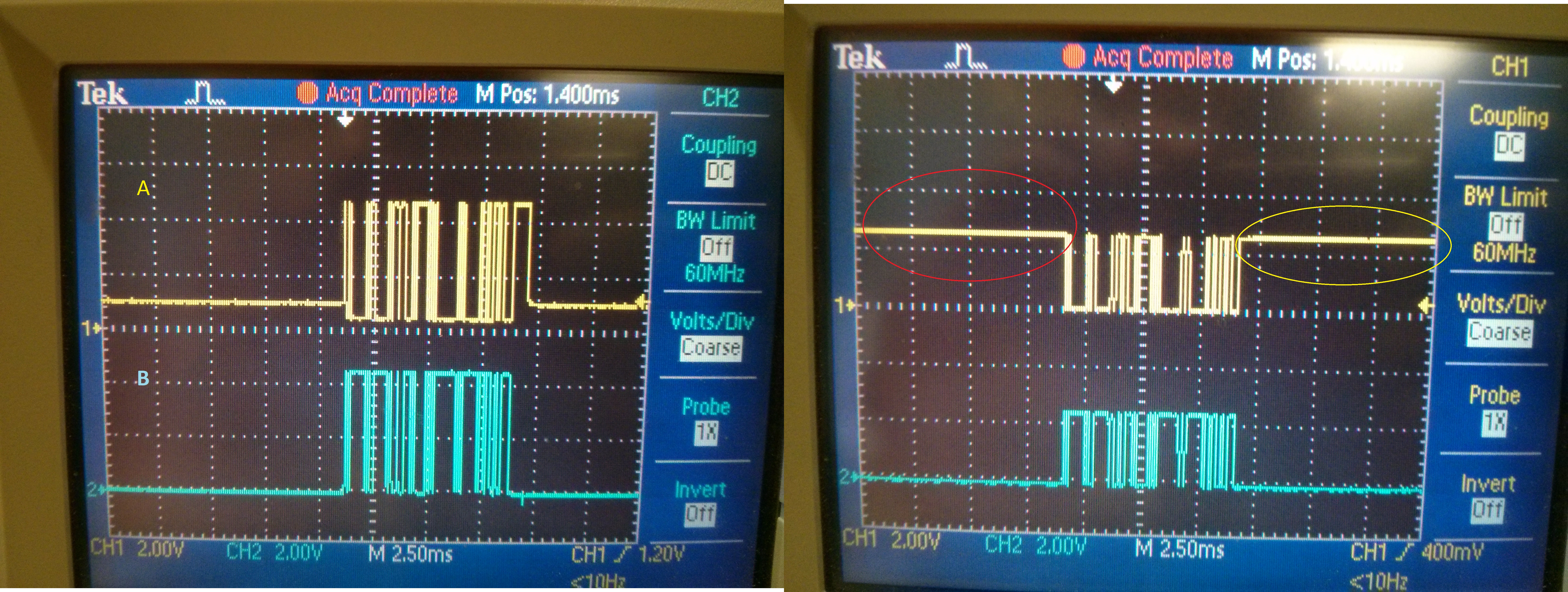
With the left one (USB - RS485 cable) I am able to control my salve, while using the msp430 (on the left), i cannot.

Any suggestion?

Thanks,

Filippo

  • You don't even mention what you do with pin 4.5 which is direction switch. Perhaps you don't switch MAX chip to receive mode when not transmitting.
  • Yes, it looks like the transmitter is not switched off after transmission. Also, I miss some biasing and load resistors in the schematics (to keep the bus on a defined state when the transmitter is off, and to limit reflections).

    As one can see, on the left picture, the bus does not return to the same low level as during transfer. This is because of the biasing resistors and the load resistor when the driver is switched off. But that’s unimportant since RS485 only needs ~200mV difference on the two lines to detect the polarity (base don the sign of the difference). The full +-3V aren’t required.

  • it seems it works now. the issue was related to some for loop before and after the trasmission


    p4.5 is enabled for the trasmission and after is enable for receiving

**Attention** This is a public forum