This thread has been locked.

If you have a related question, please click the "Ask a related question" button in the top right corner. The newly created question will be automatically linked to this question.

MSP430i2041 FET JTAG problem "Unknown device"

Other Parts Discussed in Thread: MSP430G2955, MSP430I2041, MSPWARE

Hi Gurus, 

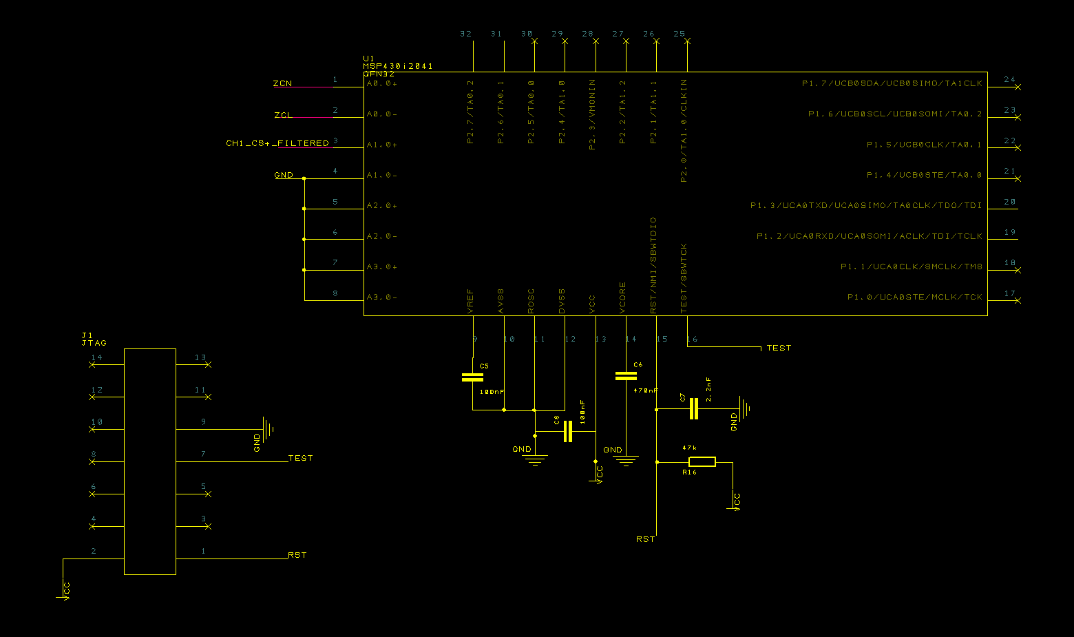
I seem to be having issue with programming the msp430i2041. I am using MSP-FET430UIF (firmware version: 3.04.03.004). The FET is working fine with other chips (I checked with MSP430G2955). I am connecting the FET directly to my board - Please check the schematic attached below. When I try to program it via CCS I get message "device unknown". Please help! I tried so far to replace the chip on the board but the result is the same.

Couple of questions I have already that maybe you have immediate answer:

1) Can I keep JTAG pins 5(TMS), 3(TDI), 11(RST/NMI) floating or should I pull them to the GND? 

2) How does FET detects that I'll be using the SBW instead of 4wire JTAG? 

Regards,

Michal

  • Hi Michal,

    Thanks for providing so much information - it is really helpful for narrowing down your issue. Looking at your schematic, the connections look correct for SBW, and the FET firmware version is new enough that it should support this device.

    -Have you ever loaded code to these devices before (e.g. did it work once and then never again)? What code?

    -Which code are you trying to load now - is it one of the TI code examples?

    The reason I ask is that the i2xx parts are different from most MSPs in that they require the code project to have some Start-Up Code (SUC) included in them that runs at startup, and if this SUC is not included in the project then the part won't start up right and you'll have problems connecting to the device - if you use the provided code examples for the part from TI Resource Explorer MSPWare in CCS, you won't have a problem because this code is already included. There are also other reasons why previously-loaded code can make it hard to load new code (e.g. an error or WDT timeout causes the part to reset before the tool can get control of it) - so this is why I was wondering if the issue occurred even with parts that were never used before and were blank.

    Another thing to try would be removing the 2.2nF pulldown Cap from the RST pin - just to see if this helps. The reason would be if there's a lot of other capacitance on this pin from long traces/wires it could maybe be causing issues with the timing for SBW on this pin.

    Michal Rogowski said:
    1) Can I keep JTAG pins 5(TMS), 3(TDI), 11(RST/NMI) floating or should I pull them to the GND? 

    I always just leave them floating (except RST/NMI - this should be pulled up, but you need this pin for SBW connection anyway - it looks like it already has correct pullup R and pulldown C in your schematic). In software you can set the other (TMS, TDI) GPIO to be pulled high or low when you aren't in JTAG mode (or use them for some other function) - the JTAG function will override the GPIO setting when the TEST pin is pulled high by the FET tool - see www.ti.com/lit/pdf/slau320 as well as the device datasheet if you want more information about the TEST pin.

    Michal Rogowski said:
    2) How does FET detects that I'll be using the SBW instead of 4wire JTAG? 

    In CCS, I believe it determines whether it should use either SBW or 4-wire JTAG by trying both of them and seeing if it gets the correct response from the device - it can put the device into either 4-wire JTAG or SBW mode by doing a different entry sequence on the TEST and RST pins (see http://www.ti.com/lit/pdf/slau320  for more information about how the FET works and entry sequences if you are curious). On some software tools like the Fet-Pro430 Lite software, you instead have to specify in the tool if you are using SBW or JTAG - it doesn't try both like CCS does. So it depends on the software being used.

    Regards,

    Katie

  • Michal Rogowski said:
    2) How does FET detects that I'll be using the SBW instead of 4wire JTAG?

    When used in CCS, by default the MSP-FET430UIF tries to auto-detect using either a JTAG or Spy-By-Wire connection to the device.


    This thread Forcing SBW mode is an example of a problem where a device couldn't be programmed in SBW when the  MSP-FET430UIF was left trying to auto-detect the connection. The referenced thread contains a modifiication to a CCS .XML file to add a GUI control to allow SBW mode to be forced - which may help in your case.

  • Hi Michal,

    Did this help resolve your issue, or are you still having problems programming the part?

    Regards,
    Katie
  • Hi Katie,

    Sorry you needed to wait for this reply so long, but I've been busy with other stuff in the meantime.

    I gave it another go today and this was the right shot:
    "Another thing to try would be removing the 2.2nF pulldown Cap from the RST pin - just to see if this helps. "
    I also inspected the TS430RHB32A and also there the 2.2nF cap is not placed.

    So the problem is solved and I can program my board now. Nevertheless I'm little concerned about leaving no cap on RST line. I understand (and might be wrong) but this CAP is intended to decouple the RST line to avoid spontaneous resets due to crosstalks etc.. Is i20x series different someway? Or should I use a smaller cap? Any good practical advice on this?
  • Hi Michal,

    I'm glad that we've narrowed down your issue. So the RST cap is as you understand supposed to help avoid glitches on the RST line that could inadvertently reset the part. However, the RST line capacitance must not exceed 2.2nF for good SBW communication on this line (can cause timing issues). Now, this can also have problems if capacitance from the board or cable from the board to the FET tool adds enough additional capacitance. So if you don't want to remove the cap completely, you can try to see if you can use a smaller value cap (1nF for example) or be able to have shorter traces + wires btwn the FET and the device?

    Regards,
    Katie

**Attention** This is a public forum