This thread has been locked.

If you have a related question, please click the "Ask a related question" button in the top right corner. The newly created question will be automatically linked to this question.

Cannot get a response from MSP430F5342 in BSL

Other Parts Discussed in Thread: MSP430F5342, MSP-EXP430F5529LP, MSP-TS430RGZ48B

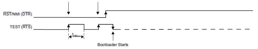
I am trying to get an MSP430F5342 to update using BSL. To give the right sequence on the TEST and RESET pins of the controller, I am using a TI MSP-EXP430F5529LP launchpad, which generates the said signals using GPIOs.

The P1.1 and P1.2 port pins of MSP430F5342, which act as Tx and Rx respectively in the BSL mode, are connected to a USB to Serial converter, which is configured to send 8 bit data, with 1 even bit parity and 1 stop bit.

I first give the TEST and RESET pin sequence to MSP430F5342, and then try to communicate to it through a COM port on a PC. According to SLAU319, the command Get BSL Version, which corresponds to 0x80 0x01 0x00 0x19 0xE8 0x62 should get a response similar to  0x00 0x80 0x05 0x00 0x3A 0x00 0x01 0x01 0x01 0x6C 0x4F. However, I am receiving no reply whatsoever from the BSL. I have tried different commands

I am unable to figure out why there is no response from the BSL. Any help would be greatly appreciated.

  • Get BSL Version is a password protected command. Did you send a correct password? Was that acknowledged?
  • Hi,
    Sorry for the late reply. I also tried sending the password, but even that is not acknowledged. The command I am using for that is:

    0x80 0x11 0x00 0x11 0xFF 0xFF 0xFF 0xFF 0xFF 0xFF 0xFF 0xFF 0xFF 0xFF 0xFF 0xFF 0xFF 0xFF 0x00 0x5C 0x38 0x4F

    This is as shown on page 27 of the SLAU319L PDF.
  • I do not have that document. But it sounds very strange to me. How could TI know the correct user defined password and put in their document?
  • It is very likely that you did not succeed in sending the BSL entry sequence to the target.
    You could do this: Load the target with a simple program to flash a LED in two different ways to indicate whether the SYSBSLIND bit in the SYSCTL register is 0 or 1. After that, the target would normally indicate it is 0. After you try to send the BSL entry sequence, what happen? Did the LED indicate it is 0, 1, or no indication at all?
  • I did as you asked, the code is as show:

    LED0_ON();
    LED1_ON();
    while(1)
    {
    	if(SYSCTL && SYSBSLIND)
    	{
    		LED0_OFF();
    		LED1_ON();
    	}
    	else
    	{
    		LED0_ON();
    		LED1_OFF();
    	}
    }

    When no sequence is applied, i.e. the MSP is left as it is, it stays in the else loop as you predicted. But, even after applying the sequence to it, the LED status indicates that it is still in the else loop. Hence, I believe that I am unable to put the MSP into BSL mode. I am unsure why that is, since the TEST and RESET sequence seems to be correct. The waveform as seen on the oscilloscope is as shown:

    I apologize for the poor quality of the image, but the waveform is similar to the one in SLAU319L, which is shown below:

    The value of t_SBW,en is 1 us according to the MSP430F5342 datasheet SLAS706E.

  • Line 6 of your code is not right. Replace the && operator with &. Please try again.

    It is also possible that BSL in the target is already disabled (unintentionally by your previous attempts) . We shall see.
  • Hi, I seem to have made a mistake while copying and editing the code so as to make it readable. But in the original code the && is replaced with &. I apologize for the confusion.
  • It seems to me that the BSL entrance sequence was not detected by the target at all.

    I know that TI documents say the timing is not critical. However, I found that some F5xx's (or FR's) are rather picky. I do not remember which, but I never tried F5342. You might want to try longer delays (up to 50 usec).
  • Hi,

    I found some part of the documentation regarding timings confusing. The part is:

    SLAU319L says:

    "The BSL program execution starts when the TEST pin has received a minimum of two positive transitions and if TEST is high while RST/NMI rises from low to high (BSL entry method, see Figure 2). This level transition triggering improves BSL start-up reliability. The first high level of the TEST pin must be at least tSBW, En (see device-specific data sheet for tSBW, En parameter)."

    Which means that the pulse width must be more than tSBW, En.

    However, in the MSP430F5432 datasheet SLAS706E it says:

    Which seems contradictory.

    When I changed the timings to make the pulse width 0.1uS, neither of the LEDs are on, but the RESET pin is high. (Hence, MSP is not in RESET. Does this mean that it is in BSL? It still does not reply to commands like Mass erase.)

    Thanks,
    Virag

  • (1) The timing requirements you quoted is for SBW operations, not for BSL entry sequence.

    (2) When neither of the LEDs are on, it means the CPU is not executing your code. It could be running the BSL code (but not working). Or it could be doing something else which we do not know.
  • Hi,

    To figure out if the problem is with the sequence or the BSL, I have modified the code on the F5342 to simply call the BSL by using the following code:

    __disable_interrupt();
    ((void (*)())0x1000)();

    Am I right in my assumption that this should remove any requirement of sending the proper sequence? In spite of that, I still cannot get any reply from the BSL. Does it mean that I need to program the BSL, and that the default BSL has somehow been corrupted?

    Thanks,
    Virag

  • According to what I read, you are correct. (But I have not used F5342 before and cannot verify that.)

    Is it possible for you to unlock BSL-Flash and inspect or dump the contents? (Using the debugger.)
  • I used the debugger to read the memory contents following 0x1000, which is the starting address for the BSL, and there appears to be a program there. Should I still try to reprogram the BSL with one of TI's releases?

  • I think it would be prudent to dump the current contents of 0x1000-0x17FF to a file and keep the file before you try to reprogram it.

    (BTW which debugger do you use? I know the one from IAR can do that with ease.)

    Virag Doshi said:
    Should I still try to reprogram the BSL with one of TI's releases?

    Not any one of TI's releases. Must be the one that is intended for for the F5342 (you may even have to match the silicon revision #)

  • I will certainly do as advised. I have the MSP-FET430UIF debugger, and use it with the Code Composer Studio. I have downloaded the release version matching with my IC. However, the BSL code is in hexadecimal form. Would you happen to know if it is possible to program it using CCS? Or do you know some other free software that I can use to program the BSL? I have tried the FET-Pro430 Lite as suggested here, but it seems unable to access the BSL's protected memory region.  

  • I do not know these things.  May be will jump in and help you.

  • Hi,


    You can use FET-Pro430 Lite to read the contents of BSL area and compare it with the expected contents.

    In the tool, make sure you enable the BSL area in Setup->Memory Options (make sure you enable the BSL segments both for Read and for Erase/Write/Verify if you are reprogramming the device).

    I recommend you to compare the contents with the released BSL image found in this software package: http://software-dl.ti.com/msp430/msp430_public_sw/mcu/msp430/MSPBSL_CustomBSL430/latest/index_FDS.html

    Select the appropriate file in FET-Pro430 Lite (Open Code File), and then click on View->Compare Code File and Flash Data.

    Besides that, can you tell us which EVM and device Rev are you using?

    I just tried a Rev F device using a MSP-TS430RGZ48B board using the BSL rocket (https://www.olimex.com/Products/MSP430/BSL/MSP430-BSL/) and BSL scripter (http://www.ti.com/tool/mspbsl).

    This is the entry sequence:

    And this is one of the commands:

    Regards,

    Luis R

  • Hi Luis R,

    If by EVM you mean Evaluation Module, then I am not using any. I have the F5342 fixed on a custom made board. As for the device Rev, my IC has the following written on it:
    MSP430F5342 TI 58I K CKZY G4.

    I am not sure how to interpret that, and which of those, if any are the device revision.

    I have some questions regarding the timings. You have given a screenshot that shows the total pulse width for the RESET pin is 2.095 ms. Are the other timings such as the TEST pin pulse width etc. critical?

    Thanks,
    Virag
  • You seem to have a Rev K, you can check a description of the marking in the errata sheet: www.ti.com/lit/pdf/slaz278

    Some MSPs have a bug restricting the timing of the BSL sequence, but this device doesn't have a restriction besides the recommended minimum state of 250ns mentioned in SLAU319

    Regards,

    Luis R

  • Hi Luis R and OCY,

    Thanks a lot for your help. The BSL works fine now that I have reprogrammed it. It appears the program was somehow either corrupt or was overwritten by some different version of BSL.

    Thank you,
    Virag

**Attention** This is a public forum